Solar Panel

a solar panel and panel technology, applied in the field of solar panels, can solve problems such as dark and unattractive to the ey

Inactive Publication Date: 2007-12-06
TRANSFORM SOLAR
View PDF8 Cites 81 Cited by
  • Summary
  • Abstract
  • Description
  • Claims
  • Application Information

AI Technical Summary

Benefits of technology

[0016] In a fifth embodiment either the element is located between the array and the panel front, or the panel front comprises the element. In this embodiment the nature of the visually distinguishable feature and/or the location of the element relative to the solar cells does not completely prevent solar light incident on the panel front from being incident on at least a portion of the array.
[0017] In a sixth embodiment the element comprises at least one...

Problems solved by technology

A disadvantage of many solar panels is that, since they are designed to absorb ...

Method used


Image

  • Solar Panel
  • Solar Panel
  • Solar Panel

Examples


example

[0197] A solar panel was constructed with the following specifications: Aperture area 1185 cm22×6 strings of 88 series-connected Sliver® solar cells.

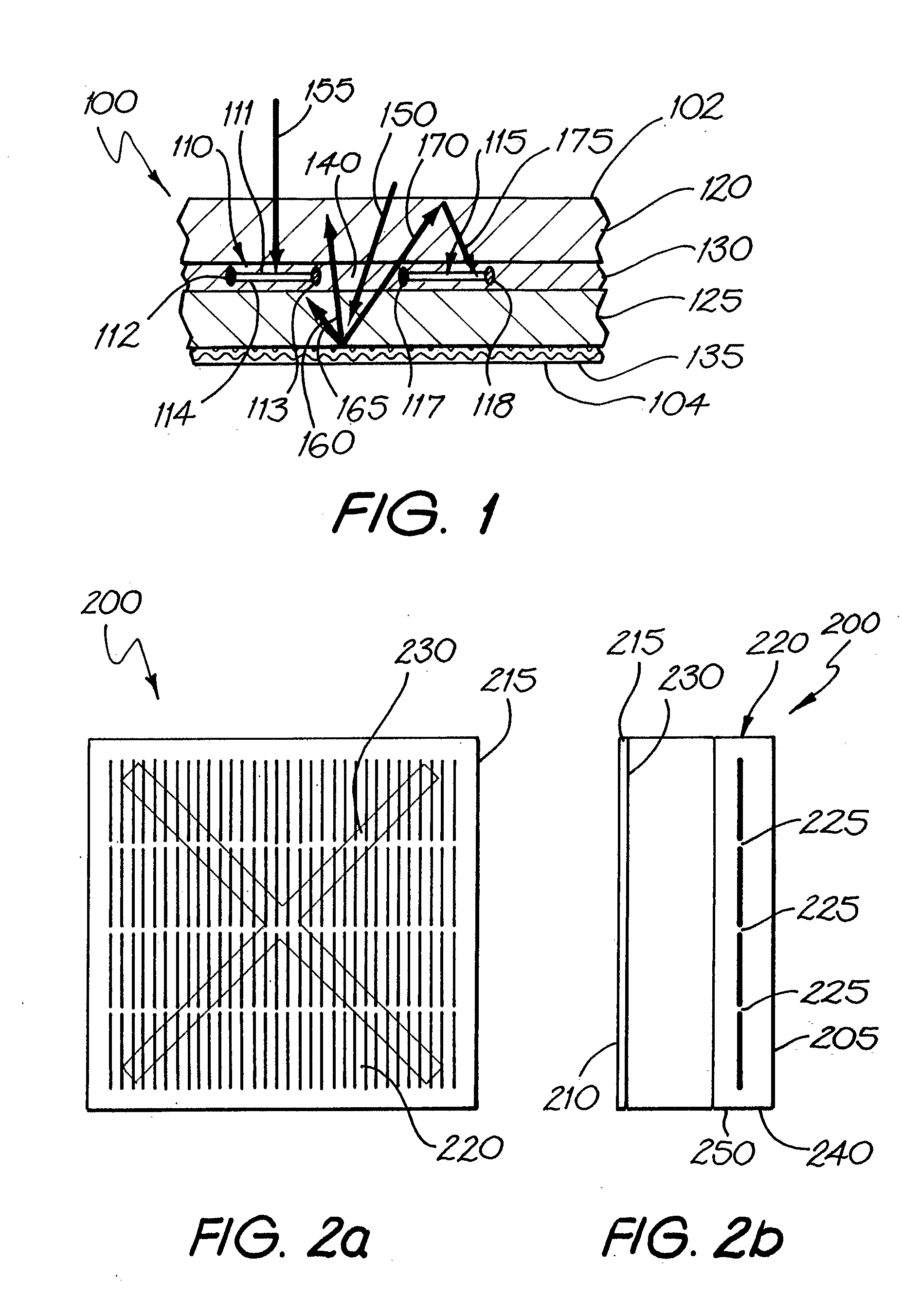
[0198] Each Sliver® cell was 1 mm×57 mm and about 65 micron thick. The Sliver® cells were bi-facial (i.e. capable of collecting light on either side).

[0199] Surface coverage of solar cells was 50%, ie there was a 1 mm gap between each solar cell.

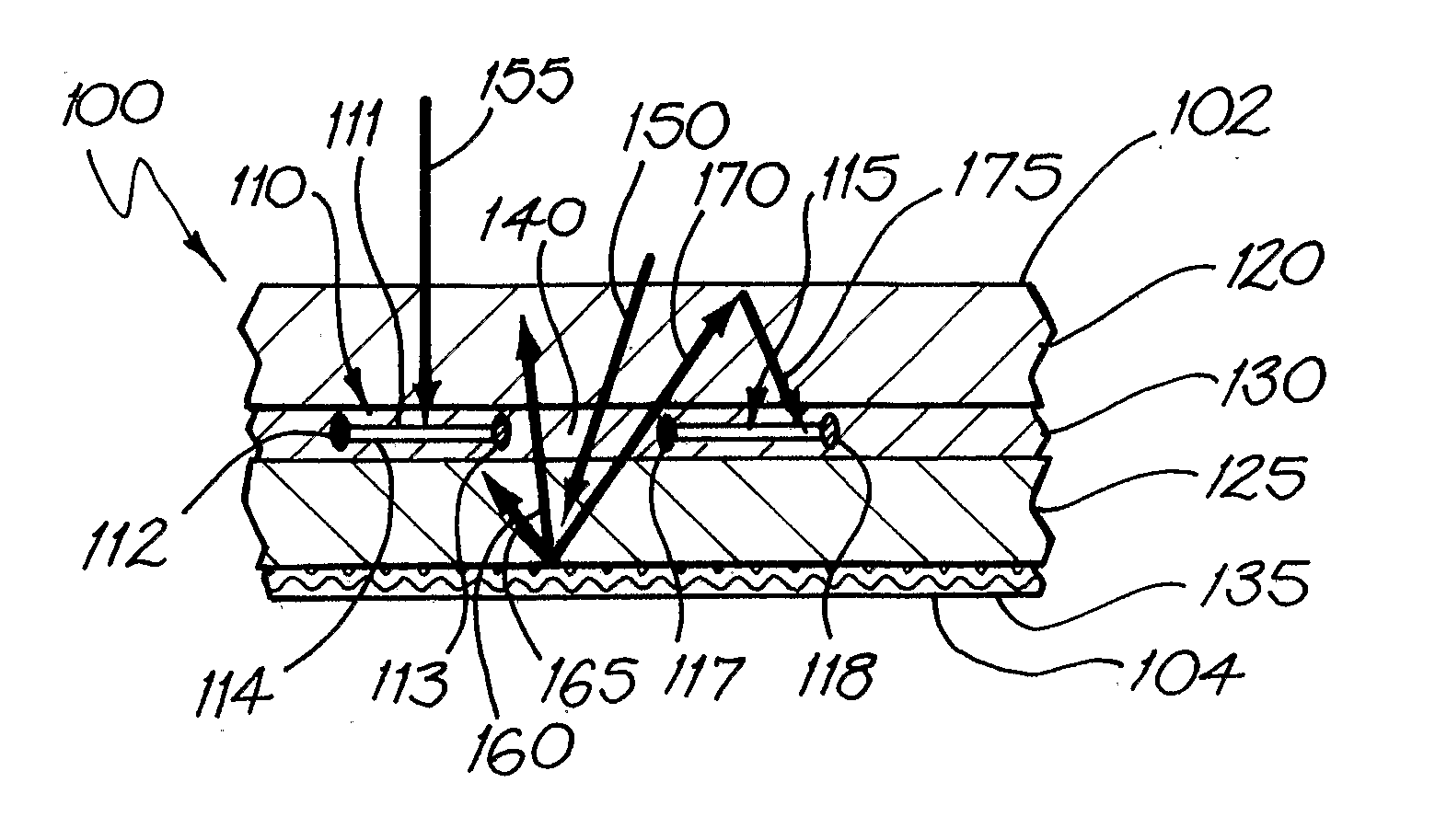
[0200] The solar cells were mounted between two panes of glass, the front pane being about 1 mm thick and the back pane being about 3 mm thick. The cells were encapsulated in an EVA encapsulant. Behind the back pane of glass was located a reflector of coloured paper (“Reflex” copy paper) as specified in Table 1. The logo was a reasonably bright pale poster. There was an air gap between the glass and the paper of about 0.1 mm.

[0201] Results for solar light collection are shown in Table 1.

TABLE 1VocIscnVocnIscnVmpnImpTest(V)(mA)(V)(mA)(V)(mA)Parallel White56.90−382.8158.13−335.9347.14−296.14...


PUM

PropertyMeasurementUnit
Fractionaaaaaaaaaa
Transparencyaaaaaaaaaa
Energyaaaaaaaaaa

Abstract

The invention provides a solar panel having a panel front and a panel back, comprising an array of solar cells and an element comprising a visually distinguishable feature. Each of the solar cells has a front and a back, wherein at least the front is capable of converting at least a portion of solar light incident thereon into electrical energy. There are spacings between at least some of the solar cells. The element comprising the visually distinguishable feature is located at at least one position selected from the group consisting of between the panel back and the panel front, on the panel front, on the panel back, at the panel front, and at the panel back, such that the visually distinguishable feature is at least partially distinguishable on viewing the panel front. The nature of the visually distinguishable feature and/or the location of the element relative to the solar cells does not completely prevent solar light incident on the panel front from being incident on at least a portion of the array.

Description

TECHNICAL FIELD [0001] The present invention relates to a solar panel having a visually distinguishable feature. BACKGROUND OF THE INVENTION [0002] Solar energy has long been considered as a renewable alternative to the energy generated from fossil fuels that is predominantly used today. Solar energy offers various advantages over more conventional power sources, and represents a clean source for generating electricity. Furthermore, solar cells do not need to be replenished with non-renewable fuels. Instead, they are powered by the effectively limitless energy from the sun. [0003] Solar energy conversion modules that convert sunlight into electrical energy typically use photovoltaic or photoelectric cells, which convert the solar energy directly into electrical energy. The amount of energy generated by a cell is directly related to the amount of solar energy the cell absorbs; the amount of energy the cell absorbs is a function of both the size or surface area of the cell and the int...

Claims


Application Information

Patent Timeline
IPC IPC(8): H01L31/042H01L31/0352H01L31/048H01L31/052H01L31/18
CPCH01L31/035281H01L31/042H01L31/048H01L31/1804H01L31/0547G09F27/007Y02E10/547Y10T29/49355Y02E10/52H01L31/049Y02P70/50
Inventor STOCK, ANDREW
Owner TRANSFORM SOLAR
Why Eureka
Try Eureka