
Pleated type cartridge filter device

a filter device and cartridge technology, applied in the direction of membranes, filtration separation, separation processes, etc., can solve the problems of reducing the service life of the filter, pattern failure, wiring failure, etc., to improve the shape holding characteristic, improve the bending stiffness of the entire filter, and save the area of the filter material.

Inactive Publication Date: 2007-12-06
ENTEGRIS INC
View PDF3 Cites 13 Cited by
  • Summary
  • Abstract
  • Description
  • Claims
  • Application Information

AI Technical Summary

Benefits of technology

"The present invention is about a cartridge filter device that has high filtration efficiency, a long filter life, and can be produced at low cost. The filter device has a unique structure called a letter W-shaped section, which includes a low mountain section on the sleeve side, two valley sections on the core side, and two high mountain sections on the sleeve side. The support material is used on at least one face of the filter material, and there is a specific ratio between the intervals of the mountain folding portions. The ratio between the outside diameter of the core and the total number of the valley folding lines is also provided. The technical effects of this invention are improved filtration efficiency, longer filter life, and cost-effectiveness."

Problems solved by technology

If foreign matter is present on the wafer or in the resist solution, the patterning cannot be carried out at a designed width, thereby resulting in a failure.
For example, even if there is left foreign matter of about 0.05 μm in a photoresist solution after filtration, fault, wiring failure, or the like may occur.
If such gel exists in the photoresist solution, insoluble foreign matter is left in a pattern to be solved by developing solution during exposure to light, of the photoresist film on a silicon wafer, thereby causing a pattern failure.
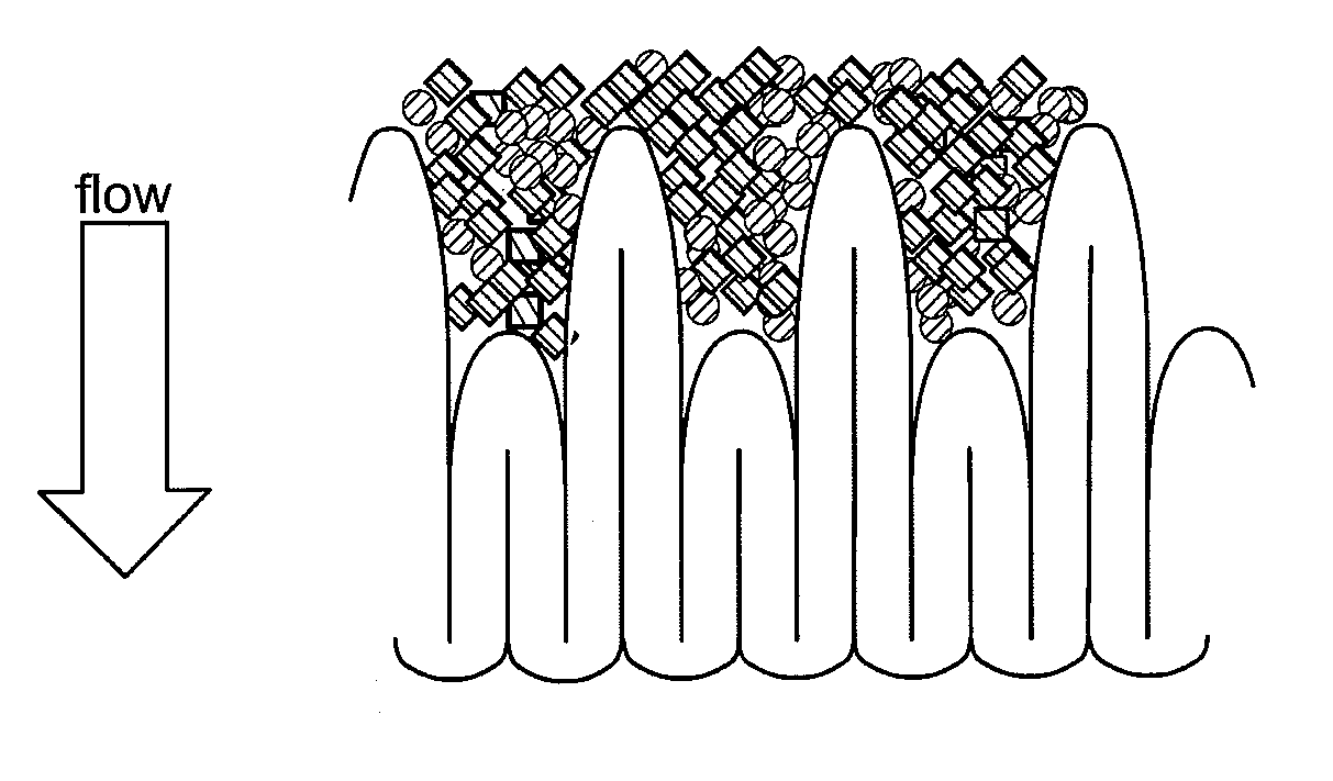
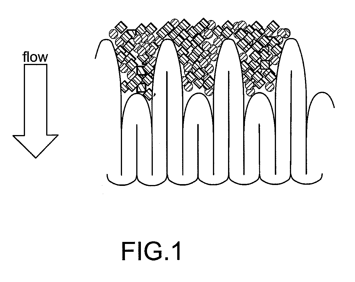
When fluid containing foreign matter is filtered by such a filter folded closely, particles not passing through the filter are deposited only on the top portion of the folded mountain so as to cause clogging.
As a result, the folded portion does not function effectively (effective filtration area is small), thereby reducing the service life of the filter (see FIG. 4).

Method used


Image

  • Pleated type cartridge filter device
  • Pleated type cartridge filter device
  • Pleated type cartridge filter device

Examples


example 1

[0045]FIG. 6a is a microscopic photograph (100×) of a filter material used in this Example. FIG. 6b is a microscopic photograph (500×) of the filter material used in this Example.

[0046] To assemble a cartridge filter device (sleeve inside diameter 76mm, core outside diameter 46mm), PFA made double cloth net (fiber diameter 0.22 mm) 450 μm in thickness as a primary side (fluid supply side) support material and PFA made thick net (fiber diameter 0.11 mm) 220 μm in thickness as a secondary side (fluid discharge side) support material were overlaid on polytetrafluoroethylene (PTFE manufactured by DAIKIN KOGYO) unwoven fabric having film area 7,022m2 with a structure shown in FIGS. 6a and b, having a coating weight of 250 g / m2 (400 μm in thickness), then pleated by repeating the repetitive unit comprised of 15 mm mountain / 12 mm mountain / 15 mm mountain (a repetitive unit comprised of high, low, high) so as to produce totally 114 mountains (76 mountains each 15 mm in height, 38 mountains ...


PUM

PropertyMeasurementUnit
sizeaaaaaaaaaa
thicknessaaaaaaaaaa
thicknessaaaaaaaaaa

Abstract

The present invention comprises a cartridge filter device having high filtration efficiency, having a long filter life, and capable of being produced at low cost. An out-in-pass-type pleated cartridge filter device has a filtration material, a core, a sleeve, and two end caps (upper and lower lid sections). In a filter material cross-section orthogonal to pleat folding, there are one mountain folding line (a), two valley folding lines (b) on both sides of the one mountain folding line, and two mountain folding lines (c) on both sides of the two valley folding lines. Thus the cartridge filter device includes a letter W-shaped section where there are one low mountain section on the sleeve side, two valley sections on the core side, on both sides of the one mountain section, and two high mountain sections on the sleeve side, on both sides of the two valley sections.

Description

CROSS-REFERENCE TO RELATED APPLICATIONS [0001] This application is a continuation of PCT Application No. PCT / JP2005 / 7263, filed Apr. 14, 2005, which designated the United States. The PCT Application claims priority from Japanese Patent Application No. 2004-120359, filed April 15, 2004.FIELD OF THE INVENTION [0002] The present invention relates to a pleated type cartridge filter device having high filtration efficiency and long filter life. More specifically, the present invention relates to a pleated type cartridge filter device having an increased area contributing to filtration (filter area), and which is capable of being produced at low cost. BACKGROUND OF THE INVENTION [0003] Filters have been used to separate foreign matter / particles in a variety of fluids and it is desirable that such filters (a) be capable of catching target foreign matter / articles, (b) be used simply / easily and (c) have a high holding capacity (accommodating capacity) for particles, that is, function to prov...

Claims


Application Information

Patent Timeline
Patent Type & Authority Applications(United States)
IPC IPC(8): B01D27/06B01D29/07B01D29/21B01D46/24B01D46/52B01D63/06B01D63/14B01D69/04
CPCB01D29/21B01D39/083B01D39/1623B01D46/2411B01D46/522B01D2313/44B01D69/046B01D2201/122B01D2239/0654B01D2239/069B01D2239/1291B01D63/067B01D29/01B01D63/14B01D29/07
Inventor KUWABARA, HIROKAZUKURATA, KOICHI
Owner ENTEGRIS INC
Learn More