Microfabricated cantilever chip

a cantilever and micro-fabricated technology, applied in the field of micro-fabricated cantilever chips, can solve the problems of putting a burden on the user, destroying or moving samples, altering samples under inspection, etc., and achieves the effect of increasing the conductivity and achieving a rather high measured resistan

Active Publication Date: 2007-12-06
FEI CO
View PDF7 Cites 32 Cited by
  • Summary
  • Abstract
  • Description
  • Claims
  • Application Information

AI Technical Summary

Benefits of technology

[0051] The IV sweep is nonlinear, even at low bias voltages <1.5V, with conductivity increasing with voltage. The electrical and thermal conductivity generally depends on temperature. The joule heating of the bridge by the dissipated power can influence the measurements depending on the temperature coefficient of resistance and thermal conductivity of the nanotube (and thermal and electrical contact resistance, which will be neglected below). A simple model can estimate the effect of the self-heating of the nanotube due to the dissipated power. To first order, the linear temperature coefficient α of resistance gives
[0052] Using ΔT=T—To one can estimate the effect of the dissipated power in the nanotube resistance if the material constants are known. For carbon fibers, α has been measured to lie in the range [−0.13; 0.02] % / K, see S. Blazewicz. B. Patalita, and Ph. Touzain. Study of piezoresistance effect in carbon fibers. Carbon, 35(10-11):1613-1618, 1997. Given the diffusive transport and defect density of the C-MWNT in this work, these values are probably reasonable estimates for the present sample. Measurements by P. Vincent, S. T. Purcell, C. Journet, and V. T. Binh. Modelization of resistive heating of carbon nanotubes during field emission. Physical Review B (Condensed Matter and Materials Physics), 66(7):075406 / 1-5, 2002 give resistance as function of temperature as R[Ω]=2*106−820ΔT and hence a value of α=−0.041%1 K, which falls within the values found for carbon fibers, although the measured resistance was rather high compared to our devices. We did attempt to do one cryogenic measurements on a NWNT on a TEM-Chip. The measured temperature coefficient was in the range [−0.2; −0.02] % / K. Based on these results the nanotubes studied here seem to have negative temperature coefficient of resistance within the expected range from α. The discussion in many published works discusses the temperature dependence of resistance. However, F. Zhou, L. Lu, D. L. Zhang, Z. W. Pan, and S. S. Xie. Linear conductance of multiwalled carbon nanotubes at high temperatures. Solid State Communications, 129(6):407-410, 2004 discussed the temperature dependence of conductance for their C-MWNT sample, which they found to be highly linear in the wide range of temperature 50-800 K. For sufficiently small αΔT<<1 the two following equations are approximately identical G=G0⁢V⁡(1-α⁢ ⁢Δ⁢ ⁢T)=G0⁢V⁡(1-α⁢L8K⁢A⁢P)(2)R=R0⁢V⁡(1-α⁢ ⁢Δ⁢ ⁢T)=R0⁢V⁡(1-α⁢L8K⁢A⁢P)(3)

Problems solved by technology

This puts a burden on the user since there is a large risk that the sample under inspection is altered during passage from one instrument to another.
It can even be destroyed or moved in position rendering measurements impossible.

Method used


Image

  • Microfabricated cantilever chip
  • Microfabricated cantilever chip
  • Microfabricated cantilever chip

Examples


Embodiment Construction

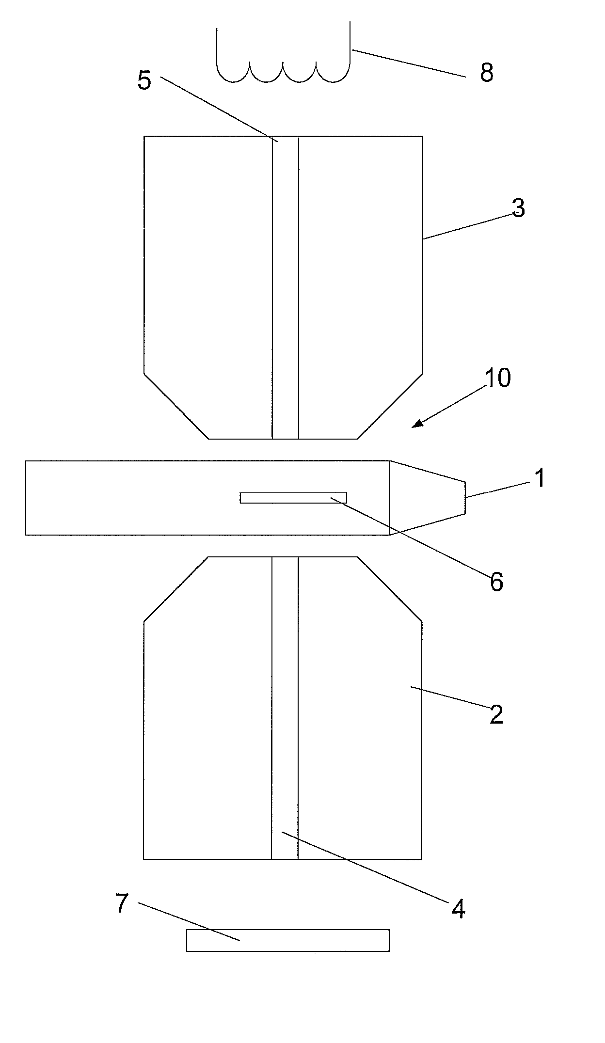
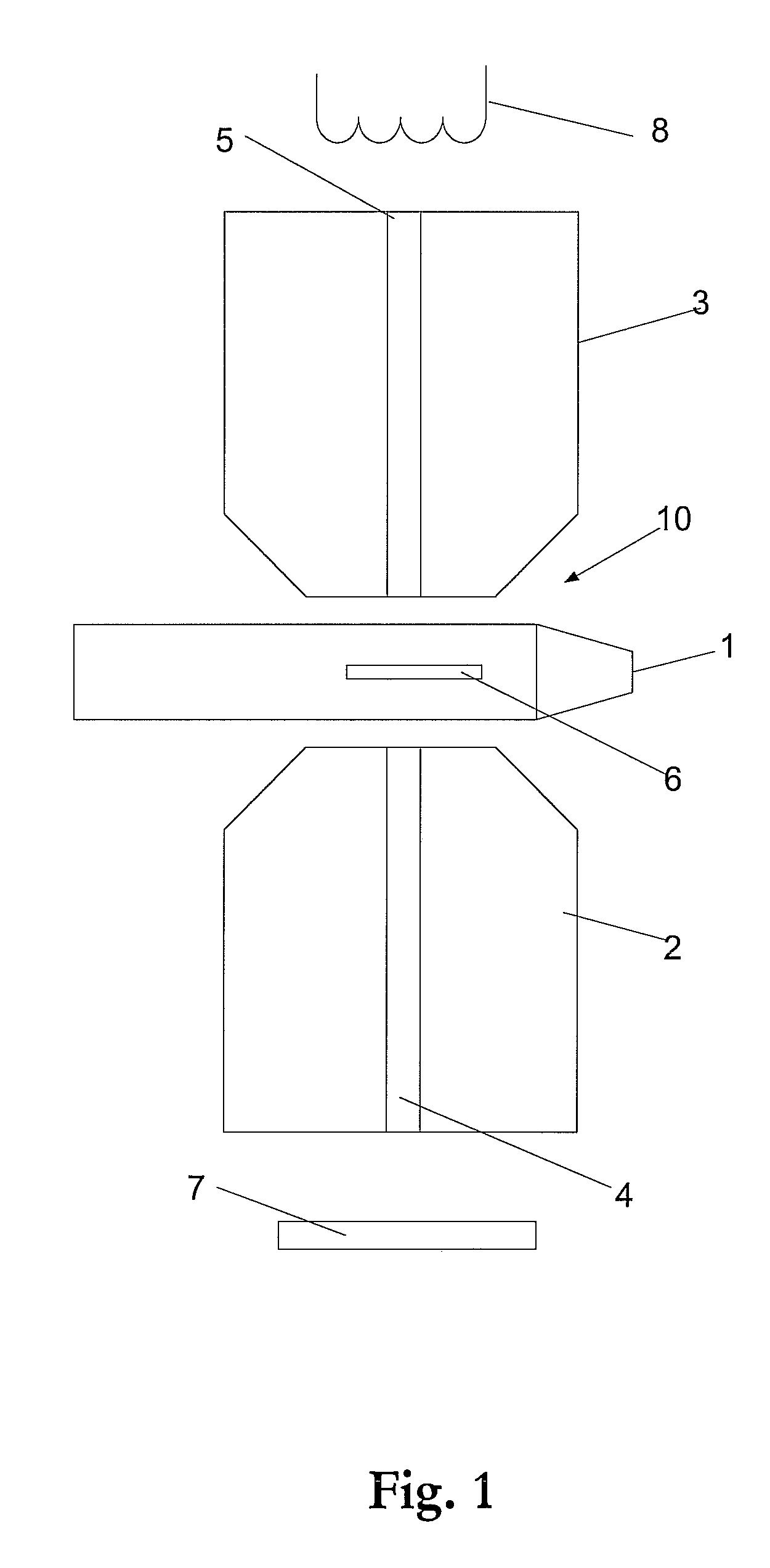
[0111] In FIG. 1, reference numeral 1 generally indicates a transmission electron microscope probe holder for use in situ of a transmission electron microscope (TEM). The probe holder is arranged during operation between two electron beam lenses 2 and 3 together forming a small gap 10 there between. Through each electron beam lens 2, 3 is an opening 4, 5 for electrons to pass through. An electron beam is formed by emitting electrons from an electron emitter 8 and the electrons are steered into a beam using the electron beam lenses 2, 3. The TEM is used for imaging small structures in a sample 6 by directing the electron beam through the sample and collecting electrons with an electron collecting device 7, such as a charge coupled device (CCD) or similar technique, sometimes also a fluorescent device may be used in order to convert the electron beam image into a photon based image for optical inspection by a user of the TEM. The TEM is a complex measurement device with a vacuum insid...


PUM

PropertyMeasurementUnit
cryogenic temperaturesaaaaaaaaaa
perimeteraaaaaaaaaa
contact resistanceaaaaaaaaaa

Abstract

The present invention relates to a device and system from doing mechanical and electrical measurements and manipulation on nano or micro sized objects using a sample holder adapted to fit in situ of a transmission electron microscope. The sample holder comprise at least two arms each with at least one connector whereby the sample (206) may be mounted between the two connectors forming a bridge closing a gap between the two arms of the sample holder. The sample holder is arranged to provide mechanical forces to a sample mounted on the sample holder and measuring and/or applying electrical signals from the sample while at the same imaging using the transmission electron microscope. Each arm of the sample holder may comprise three substantially parallel beams for electro-thermal actuation.

Description

TECHNICAL FIELD [0001] The present invention relates to a micro fabricated cantilever chip and in particular to a micro and nano gripping device for use in transmission electron microscopes. BACKGROUND OF THE INVENTION [0002] Research and development of and on micro and nano sized objects and systems have received considerable interest the last few decades and have accelerated the last decade during the advent of nanotechnology. Doing work on objects of this scale set demands on the instrumentation and techniques used in order to be able to manipulate, assemble, measure and do testing on these objects. Several different measuring devices have been developed in order to do some of these types of activities, often instrumentation is designed for specific purposes, for instance the atomic force microscope is used for obtaining images of force interactions between a surface and a probe of surfaces down to atomic resolution at it's best, scanning electron microscopy and transmission elec...

Claims


Application Information

Patent Timeline
Patent Type & Authority Applications(United States)
IPC IPC(8): G21K5/10G01K5/08
CPCB25J7/00B25J15/12H01J2237/2007B82Y35/00B81C99/002
Inventor MOLHAVE, KRISTIAN
Owner FEI CO
Why Eureka
Try Eureka