Ink jet printing system for high speed/high quality printing

a printing system and high-speed technology, applied in the field of image printing, can solve the problems of non-archival images, difficult to achieve high image densities, and non-uniform printing

Inactive Publication Date: 2007-12-06
EASTMAN KODAK CO
View PDF58 Cites 42 Cited by
  • Summary
  • Abstract
  • Description
  • Claims
  • Application Information

AI Technical Summary

Problems solved by technology

However, inks having only non-volatile polar oils as the liquid carrier can give rise to a problem that the solvent remains on the printings for a long time, and the residual solvent is apt to cause “strike-through”, where the ink can be seen through from the back side of the print, and/or smearing.
As a result, high image densities are difficult to achieve, image drying is not trivial, and images are not archival because many dyes are disadvantageously subject to fading.
In continuous ink jet printers using pigmented inks, the relatively high concentrations of pigment typically affects the droplet break-up, which tends to result in non-uniform printing.
A deficiency associated with most high resolution conventional ink jet devices that deposit ink directly on to a (porous) paper receiver is an unavoidable tendency for image spreading, with a concomitant resulting degradation of resolution and sharpness of the image produced.
As a drop of deposited liquid ink is absorbed, capillary forces tend to draw the ink along the receiver surface and into the micro-channels between paper fibers, thereby causing a loss of resolution.
This also holds true for the case of pigmented aqueous based inks, for which particle sizes may be sub-micron; i.e., such very small particles can be swept along by the carrier liquid as it spreads in the paper receiver, thereby compromising high resolution imaging quality.
In addition to capillary spreading by liquid absorption in a receiver, spreading may also be a problem if the carrier liquid is not readily absorbed by a receiver; e.g., if the receiver is a coated specialty paper used in a high resolution conventional ink jet device that deposits ink directly on to a receiver.
Another limitation of ink jet printing is that the image density tends to be low.
As the ink is absorbed into the paper, the paper fibers show through the ink, thereby limiting the density.
The low viscosity limits the amount of colorant that can be present, thereby limiting the image density that can be obtained.
A limitation of printing at high speed with ink jet technology arises from the amount of liquid used in ink jet printing.
Thus, the image on the receiver has relatively large amounts of ink, which need to be dried before the image is usable.
At high speeds, this drying step is complex and energy-intensive.
Ink jet printing currently cannot generally achieve printing quality as high as can be achieved using offset printing techniques, especially at high speeds.
Ink jet printing is typically slower than traditional offset printing.
This represents a major issue limiting the implementation of ink jet technology in industrial printing systems.
However, at high speeds, the results tend to be poor due to the di

Method used


Image

  • Ink jet printing system for high speed/high quality printing
  • Ink jet printing system for high speed/high quality printing
  • Ink jet printing system for high speed/high quality printing

Examples


example 1

[0063]Formation of stable drops in an ink jet apparatus using a high percent solids, shear-thinning ink.

Description of Ink:

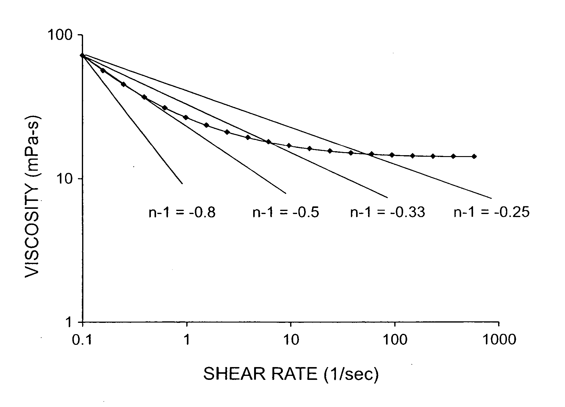
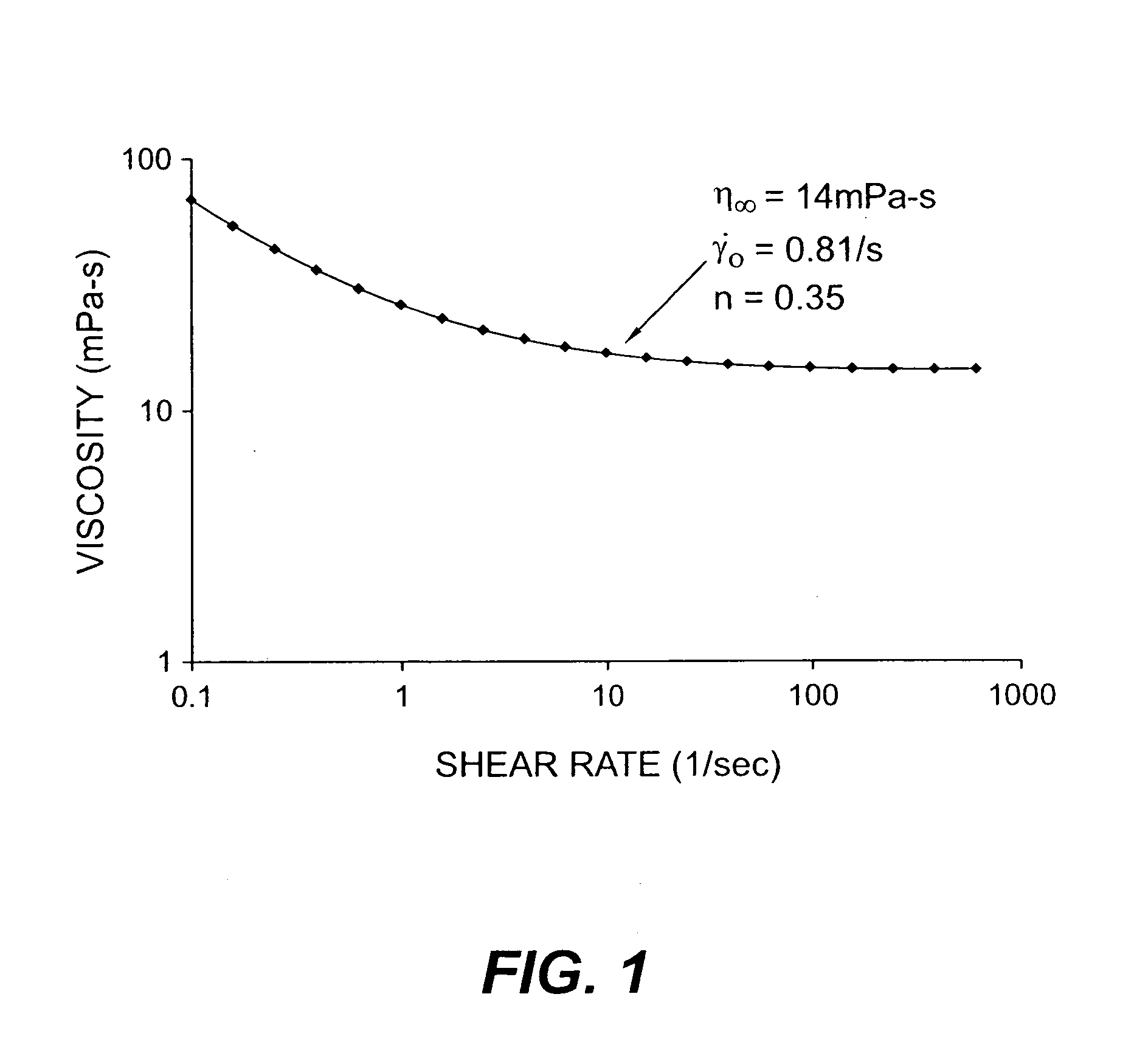
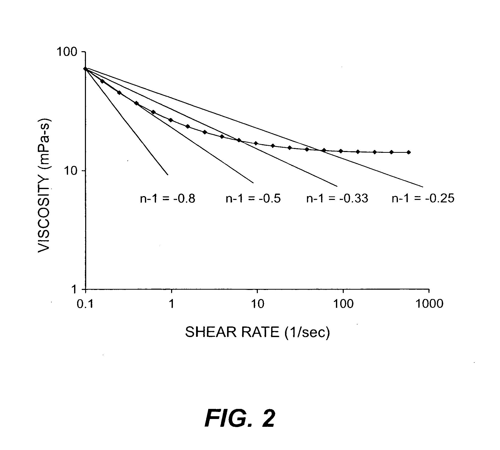
[0064]A gravure ink from Flint Group, called Arrowvure 5 Cyan Blue® was used in the jetting experiment. The ink contained 34.44% solids, a surface tension of 31.7 dynes / cm, a pH of 9.46 and a median particle size of 0.105 microns as measured by light scattering using a Microtrac® UPA 150 instrument. The rheology of the ink was measured with an Advanced Rheometric Expansion System (ARES®) rheometer by Rheometric Scientific. This instrument controls strain (rotational velocity in a given geometry) and measures stress (torque). The testing geometry used to analyze the sample was a large Couette (concentric cylindrical bob in cup) with a cup diameter of 34 mm, a bob diameter of 32 mm, a bob length of 33.4 mm, and bob height above cup bottom of 4.0 mm. Steady shear rate sweeps were performed at the desired test temperatures of 25° C. and 50° C. For the 50° C. runs, t...

example 2

[0070]Formation of prints on various receivers from an ink jet apparatus using high-percent solids, shear-thinning ink.

[0071]The ink used was the same ink as described in Example 1, except 2 wt. % Dapro DF-1760 defoamer (from Elementis Corp.) and 5 wt. % glycerol were added. The final ink contained 30.17 wt. % solids, a surface tension of 32.0 dynes / cm, a pH of 9.38 and a median particle size of 0.0964 microns. Table 3 gives the viscosity of the ink equilibrated at 25° C. at shear rates from 0.1 / s-1,000 / s. The data in Table 3 show that the ink is shear-thinning at a temperature of 25° C.

TABLE 3Viscosity (mPa-s)Ink in Example 2Shear Rate (1 / s)T = 25° C.0.10018.660.15815.150.25113.610.39812.070.63111.011.00010.241.5859.452.5128.953.9818.536.3108.1610.007.9315.857.7425.127.5939.817.4363.107.33100.07.26158.07.23251.07.27398.07.32631.07.451,000.07.60

[0072]The receivers shown in Table 4 were used upon which to print the ink in Example 2:

TABLE 4ReceiverInternational Paper Carolina Cover CI...


PUM


Abstract

In an ink jet printing apparatus for high speed/high quality printing, an ink jet ink having a high concentration of solids the range of about 20-70 wt. %, and exhibiting shear-thinning characteristics.

Description

FIELD OF THE INVENTION[0001]This invention relates in general to image printing in an apparatus including an ink jet printing device, and more particularly to ink jet printing for high speed / high quality printing utilizing high solids shear-thinning inks in ink jet printhead devices.BACKGROUND OF THE INVENTION[0002]High-resolution digital input imaging processes are desirable for superior quality printing applications, especially high quality color printing applications. As is well known, such processes may include electrophotographic processes using small particle dry toners, e.g., having particle diameters less than about 7 micrometers, electrostatographic processes using non-aqueous, solvent based liquid developers (also referred to as liquid toners) in which the particle size is typically on the order of 1 micrometer or less, and ink jet processes. Ink jet recording systems employ either aqueous inks using water as the main liquid carrier where the drying involves absorption, pe...

Claims


Application Information

Patent Timeline
IPC IPC(8): G01D11/00
CPCC09D11/30C09D11/101
Inventor REGAN, MICHAEL THOMASBRICK, MARY CHRISTINEGELBART, DANIELGARBACZ, GREGORY JAMESYACOBUCCI, PAUL D.
Owner EASTMAN KODAK CO
Why Eureka
Try Eureka