Seal device for a fluid machine

a fluid machine and sealing device technology, applied in the direction of machines/engines, stators, liquid fuel engines, etc., can solve the problems of reducing the efficiency of fluid machines, and limiting the reduction of leakage, so as to reduce leakage losses, increase the efficiency of fluid machines, and prevent vibration

Inactive Publication Date: 2007-12-06
TORISHIMA PUMP MFG CO LTD
View PDF13 Cites 17 Cited by
  • Summary
  • Abstract
  • Description
  • Claims
  • Application Information

AI Technical Summary

Benefits of technology

[0007]It is an object of the present invention to provide a seal device for preventing leakage of a fluid from a high pressure area to a low pressure area in a casing of the fluid machine through a gap between the casing and a rotor disposed in the casing, wherein the device can minimize the amount of leakage, reduce vibrations, prevent seizure, and inhibit wear and cavitation with achieving relatively simple structure and easy manufacturing and maintenance.
[0008]Thus, the present invention provides a seal device for a fluid machine for preventing leakage of a fluid from a high pressure to a low pressure area in a casing of the fluid machine through a gap between the casing and a rotor disposed in the casing, comprising, a main ring having a single-piece structure, fixed to a portion of the casing corresponding to a boundary between the high pressure area and the low pressure area, being formed therein with a main through bore which extends between the high pressure area and the low pressure area and into which the rotor is inserted so as to define a first gap between an inner peripheral wall of the main through bore and an outer peripheral surface of the rotor, and a thin auxiliary ring having an outer circumferential portion accommodated in an annular accommodation groove formed at a portion of the inner peripheral wall of the main through bore at a high pressure area side, being formed therein with an auxiliary through bore of a smaller outer diameter than that of the main through bore which extends between the high pressure area and the low pressure area and into which the rotor is inserted so as to define a second gap narrower than the first gap between an inner peripheral wall of the auxiliary through bore and the outer peripheral surface of the rotor.
[0009]Because the thin auxiliary ring is provided as a separate element from the main ring, the diameter of the auxiliary through bore formed in the thin auxiliary ring can be set much less than the diameter of the main through bore formed in the main ring so as to set the second gap much narrower than the first gap. As a result, the amount of fluid leaking from the high pressure area to the low pressure area through the first and second gaps can be minimized. Such reduction in the amount of fluid leakage can decrease leakage losses, thereby increasing an efficiency of the fluid machine.
[0010]The thin auxiliary ring is provided as the separate element from the main ring, and the gap (second gap) between the inner peripheral wall of the auxiliary through bore formed in the thin auxiliary ring and the outer peripheral surface of the rotor is set less than the gap (first gap) between the inner peripheral wall of the main through bore formed in the main ring and the outer peripheral surface of the rotor. As a result, the rotor and the main ring (inner peripheral wall of the main through bore) are not in contact with one another, thereby preventing the vibration due to contact of the rotor with the main ring and preventing the seizure between the rotor and the main ring.
[0011]The first gap at the main ring side is located on the low pressure area side with respect to the second gap at the thin auxiliary ring side, and the first gap is wider than the second gap. Therefore, the flow rate of fluid flowing through the first gap from the high pressure area side to the low pressure area side can be reduced and, thereby preventing wear of the main ring (wear of the inner peripheral wall of the main through bore). Further, because the flow rate of the fluid flowing in the vicinity of the exit of the first gap on the side of the low pressure area is reduced, the rapid pressure drop in this portion does not occur, thereby preventing the cavitation.
[0012]Both the main ring and the thin auxiliary ring have single-piece structures constituted by a single component rather than structures obtained by assembling a plurality of components, and the thin auxiliary ring can be easily assembled to the main ring by merely bending the thin auxiliary ring to be fitted in the annular accommodation groove of the main ring. Therefore, the seal device according to the present invention can be easily manufactured. Further, if necessary, the thin auxiliary ring can be removed from the main ring by bending the thin auxiliary ring and to be pulled out from the annular accommodation groove of the main ring, and then a new thin auxiliary ring for replacement can be assembled to the main ring by bending the new thin auxiliary ring to be fitted into the annular accommodation groove of the main ring. Accordingly, the seal device according to the present invention can be easily maintained.

Problems solved by technology

First, where the gap between rotor and the inner peripheral surface of the wear-ring is set too small for reducing the fluid leakage, assemble of the wear-ring and rotor is impractical. This is caused by size errors or assembling errors inevitably occur even if the wear-ring and rotor are machined with highly precise machining accuracy. Therefore, the gap size needs to be set to a certain level with consideration for assembling, thereby placing limitation on possible leak reduction.
Further, vibrations occur due to contact of the rotor and wear-ring during operation of the fluid machine, and these vibrations can cause seizure.
However, because the lining wears off due to contact of the rotor and wear-ring, long term operation of the fluid machine can cause exposure of the metal material covered by the lining which results in seizure.
The fluid flowing with the high flow rate passing through the gap causes wear of the wear-ring In addition, in a vicinity of an exit at the lower pressure side of the gap, rapid pressure drop due to remarkably increased flow rate can cause cavitation by which vibrations and wearing are occurred.

Method used


Image

  • Seal device for a fluid machine
  • Seal device for a fluid machine
  • Seal device for a fluid machine

Examples


Embodiment Construction

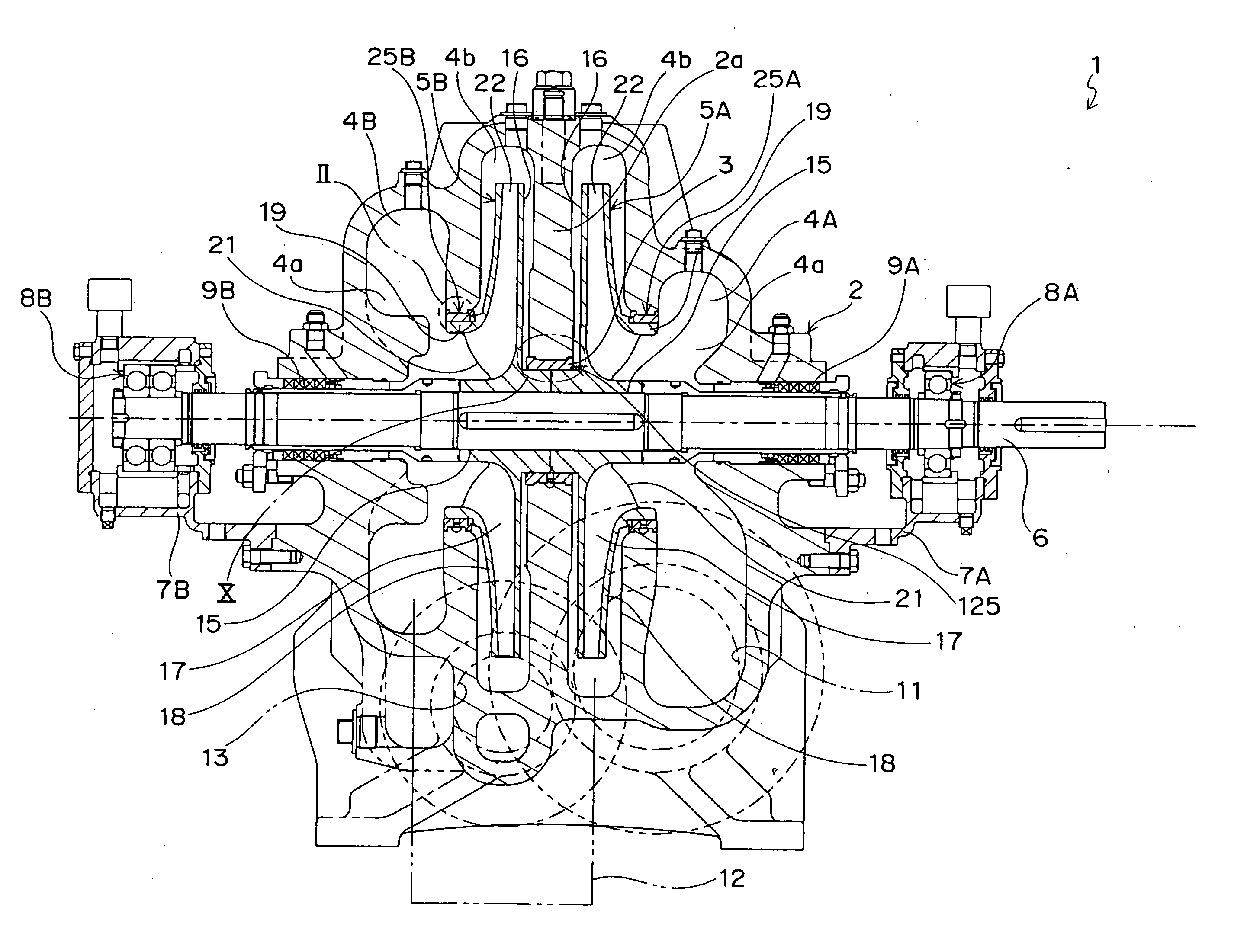
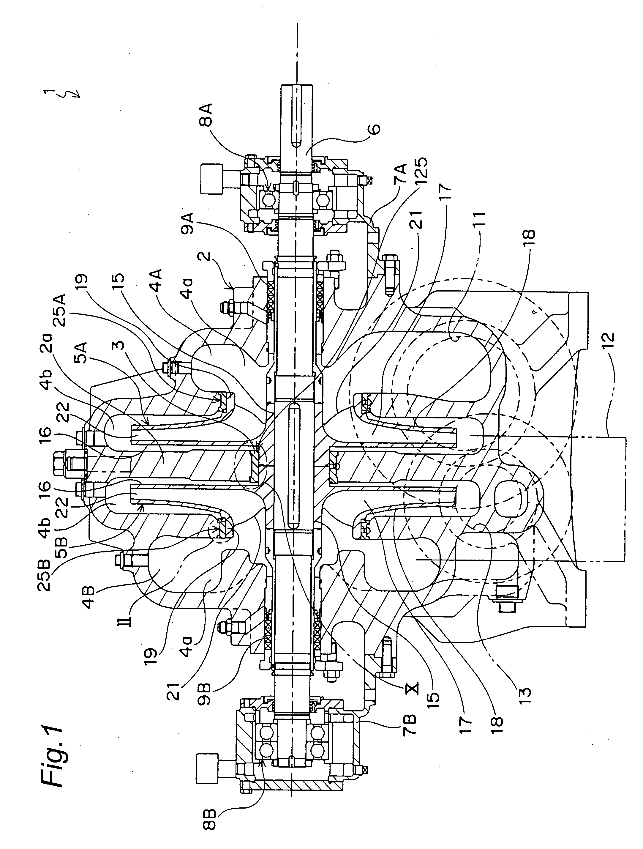
[0025]FIG. 1 shows a two-stage centrifugal pump 1 comprising seal devices according to embodiments of the present invention. First stage and second stage volute sections 4A, 4B are formed inside a casing 2 of the centrifugal pump 1. Positioned between the first stage volute section 4A and the second stage volute section 4B is a partition portion 2a of the casing 2, to which an inter bush 3 is fixed as described later in detail. A first stage impeller 5A and a second stage impeller 5B are respectively disposed, with a left-right symmetry, in the volute sections 4A, 4B. These impellers 5A, 5B are fixed to a main shaft (rotary shaft) 6 extending in the horizontal direction. The main shaft 6 extends through the casing 2. A pair of bearing brackets 7A, 7B are fixed to the casing 2, and both ends of the main shaft 6 are rotatably supported by bearings 8A, 8B accommodated in these bearing brackets 7A, 7B. Further, a pair of gland packing 9A, 9B for sealing is respectively installed in port...


PUM


Abstract

A seal device 25B has a wear-ring 31 fixed to a casing 2 of a centrifugal pump and a floating ring 32. An annular gap 36 between an inner peripheral surface of a through bore 32a formed in the floating ring 32 and an outer peripheral surface of a mouth ring portion 19 of an impeller 5B is smaller than an annular gap 35 between an inner peripheral surface of a through bore 31a formed in the wear-ring 31 and the outer peripheral surface of the mouth ring portion 19. Fluid leakage from a high pressure area to a low pressure area in the casing 2 through the gaps is prevented.

Description

BACKGROUND OF THE INVENTION[0001]The present invention relates to a seal device for a fluid machine (turbo machine) such as a pump, turbine, compressor, and gas turbine. Particularly, the present invention relates to a seal device for preventing leakage of a fluid from a high pressure area to a low pressure area in a casing of the fluid machine through a gap between the casing and a rotor disposed in the casing.[0002]An example of a seal device installed between a casing and a rotor such as a main shaft or an impeller of a fluid machine is disclosed in Japanese Utility Model Application Laid-open Publication No. 6-018694. The seal device uses a wear-ring. Specifically, a gap is formed between an inner peripheral surface of the wear-ring fixed to the casing and an outer peripheral surface of the rotor, and a size of the gap is set to as small as possible, thereby preventing the fluid leakage from a high pressure side to a low pressure side via the gap.[0003]However, the conventional ...

Claims


Application Information

Patent Timeline
Patent Type & Authority Applications(United States)
IPC IPC(8): F04D29/08
CPCF04D29/162F04D29/167
Inventor KANEMORI, YUJI
Owner TORISHIMA PUMP MFG CO LTD
Why Eureka
Try Eureka