Optically coupled endoscope with microchip

a microchip and endoscope technology, applied in the field of endoscope devices, can solve the problems of increasing the weight and cost of the device, limited success in addressing the problem, and the problem of electrical isolation continues to be a problem

Inactive Publication Date: 2007-12-06
KARL STORZ ENDOVISION INC
View PDF19 Cites 120 Cited by
  • Summary
  • Abstract
  • Description
  • Claims
  • Application Information

AI Technical Summary

Benefits of technology

[0013]It is contemplated that the digital imaging device may comprise, in an advantageous embodiment, a C-MOS chip utilizing a solar cell to transform the optical energy into electrical energy for powering of the C-MOS chip. It should be noted, however, that the digital imaging device may further comprise, for example, a CCD or other suitable image generating device as desired. The image data may further be converted into optical ener

Problems solved by technology

While these systems have provided a degree of electrical isolation and thereby increased safety for the patient, electrical isolation continues to be a problem especially due to the fact that additional medical devices (e.g. endoscopes) that are not electrically isolated are in the direct vicinity of the working area forming an electrical path from the patient to associated equipment.
There has been limited success in addressing this problem.
While this system does provide a measure of electrical isolation for the power supplied to the endoscope, this still does n

Method used


Image

  • Optically coupled endoscope with microchip
  • Optically coupled endoscope with microchip
  • Optically coupled endoscope with microchip

Examples


Embodiment Construction

[0027]Referring now to the drawings, wherein like reference numerals designate corresponding structure throughout the views.

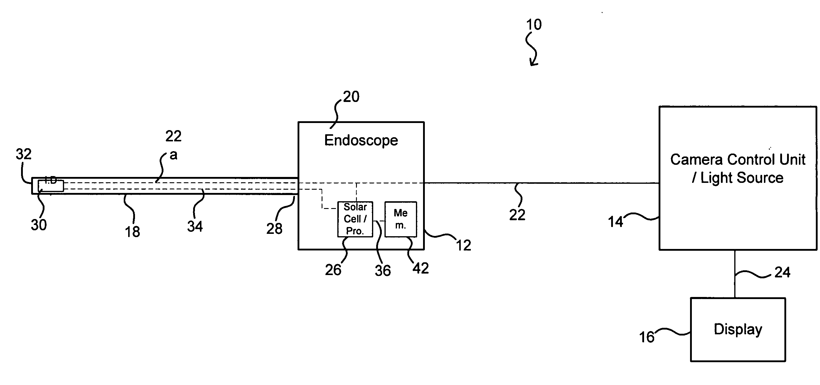
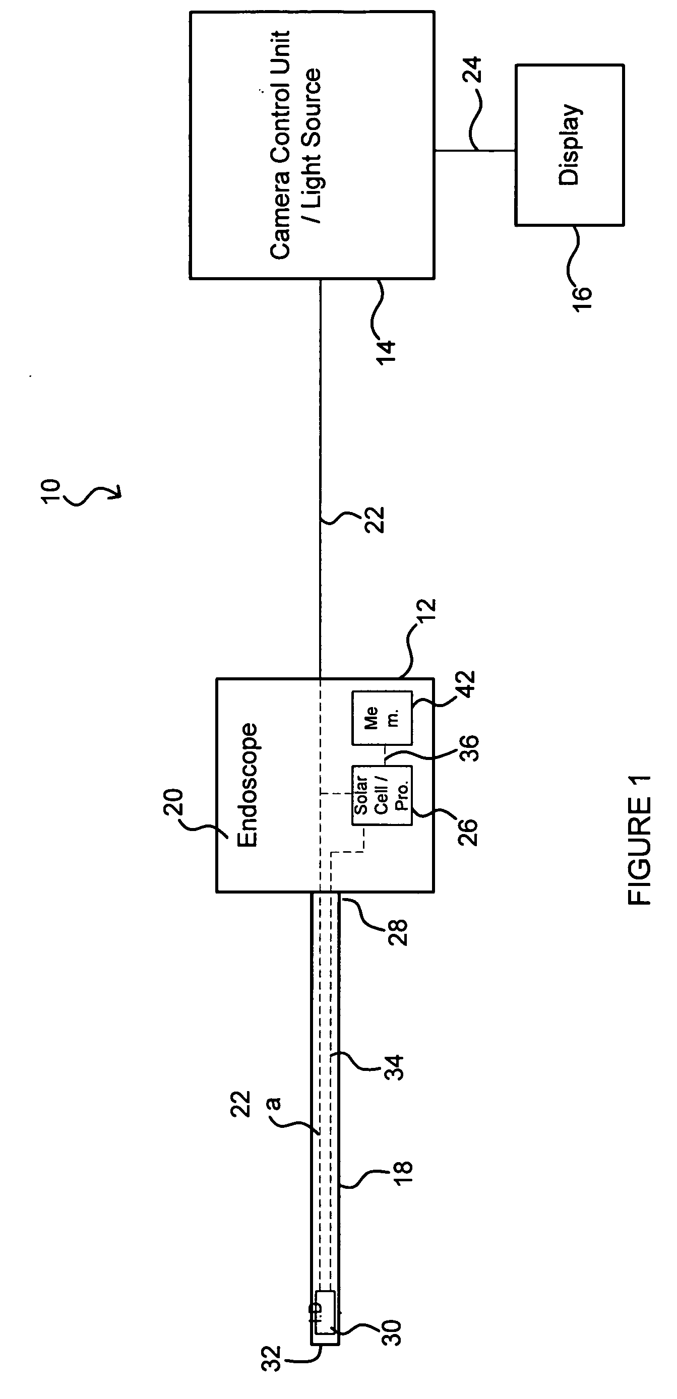
[0028]FIG. 1 is an illustration of an advantageous embodiment of system 10, which generally includes endoscope 12, camera control unit 14 and display 16. Endoscope 12 may include a shaft 18 (rigid or flexible) and a handle portion 20. Endoscope 12 is coupled to camera control unit 14 via optical channel 22, which may comprise a set of coherent optical fibers. It is contemplated that optical channel 22 may be permanently or detachably connected to endoscope 12 and / or camera control unit 14.

[0029]As indicated on FIG. 1, camera control unit 14 may be provided with a light source, which may in one advantageous embodiment, be integral with camera control unit 14.

[0030]Display 16 may comprise virtually any type of video screen display for presenting video images to the physician. The display 16 is illustrated coupled to camera control unit 14 via connection 24, which...


PUM


Abstract

An endoscope device providing electrical isolation between the endoscope and a camera control unit coupled to the endoscope. The endoscope uses an optical channel to transmit illuminating light to the endoscope and to transmit image data generated by an imaging device to the camera control unit. In this manner, only an optical connection between the endoscope and the camera control unit exits. Alternatively, a wireless channel for transmission of the image data and any commands signals may be utilized.

Description

FIELD OF THE INVENTION[0001]The invention relates to an endoscope device that provides a relatively high level of electrical isolation to a patient, and more specifically, the invention relates to and endoscope device that effectively electrically isolates the patient from connection to an electrical power source during a surgical procedure.BACKGROUND OF THE INVENTION[0002]Endoscope devices have been used for minimally invasive surgical procedures for some time providing significant advantages for the patient. Endoscopes, whether a direct viewing type provided with, for example, and eye piece for the physician to look through, or video endoscopes including a camera to pick up and transmit images to a screen for viewing by the physician, allow for viewing of a surgical area. Typically, endoscopes are provided with an illuminating light source to provide illumination of the cavity for viewing by the physician.[0003]With the advent of numerous electrical and electronic surgical devices...

Claims


Application Information

Patent Timeline
IPC IPC(8): A61B1/04
CPCA61B1/00029A61B1/00036A61B1/00013A61B1/05A61B2560/0214A61B1/0008
Inventor HOPKINS, VERNONLANDRY, DANA J.
Owner KARL STORZ ENDOVISION INC
Why Eureka
Try Eureka