Polymer-and polymer blend-bioceramic composite implantable medical devices
- Summary
- Abstract
- Description
- Claims
- Application Information
AI Technical Summary
Benefits of technology
Problems solved by technology
Method used
Image
Examples
example 1
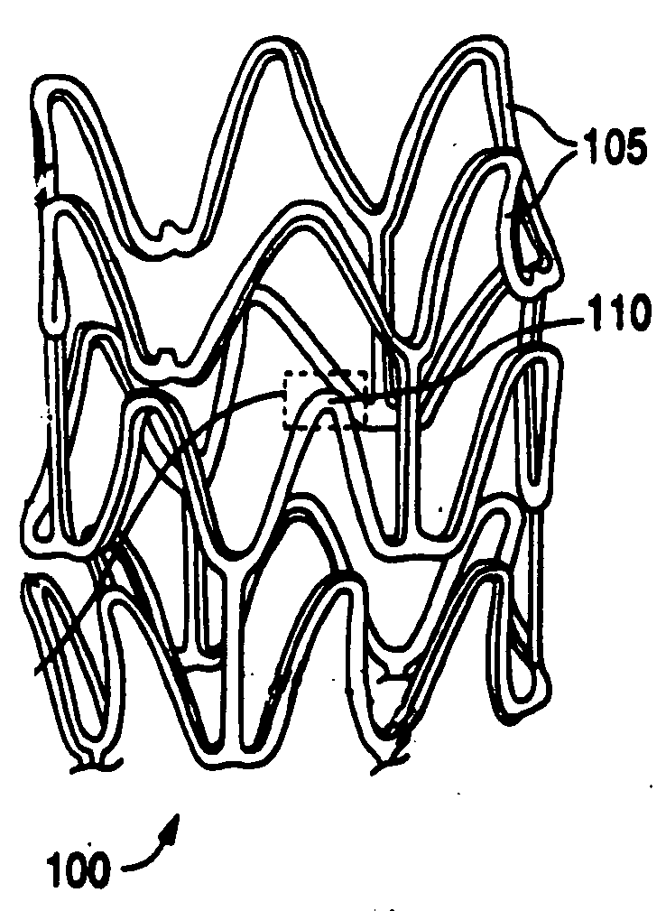
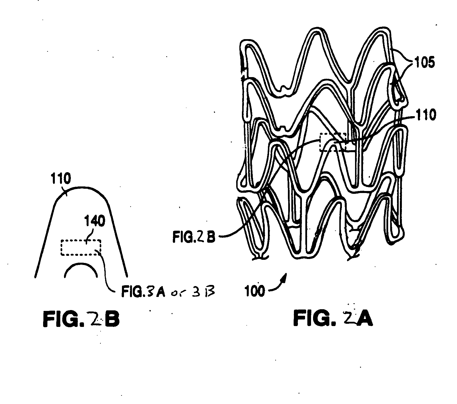
[0140]Stents were fabricated from a polymer blend / bioceramic composite. PLLA is the matrix polymer and P(GA-co-CL)-b-PLLA and / or PLLA-b-P(GA-co-CL) is the modifier polymer. Calcium sulfate nanoparticles are the bioceramic nanoparticles. Calcium sulfate nanoparticles, were pretreated by PEG-PPG-PEG surface modifier. PEG refers to polyethylene glycol and PPG refers to polypropylene glycol. The weight ratio of matrix polymer to modifier polymer to bioceramic particles was 100:10:1.
[0141]The composite was fabricated according to methods described herein. The stents were fabricated from tubes made from the composite and the tubes were radially expanded. The expanded tubes were laser cut to form stents.
[0142]Compression, recoil, or expansion testing were performed on stent samples. Two different in-house crimpers were used, referred to here as crimper No. 1 and crimper No. 2. The stents were tested at a zero time point, i.e., after fabrication without aging.
example 2
[0153]Stents were fabricated from a polymer blend / bioceramic composite with LPLG as the matrix polymer and P(GA-co-CL)-b-LPLG as the modifier polymer.
[0154]1. LPLG / P(GA-co-CL)-b-LPLG / nano bioceramic tubing preparation: 100 portions of LPLG (85:15), 10 portions of in-house prepared P(GA-co-CL)-b-LPLG copolymer, and 1 portion of nano bioceramic were mixed together and then extruded at 210° C. to form polymer tubing. The wall thickness of the formed tubing was about 0.050 inch and the outer diameter (OD) was about 0.072 inch.
2. Stent Preparation
[0155]The extruded tubing was radially expanded for higher radial strength. The stent was then cut from the radially expanded tubing and sterilized by an electron beam. The wall thickness of the final stent was about 0.005 inch and the OD was about 0.052 inch.
3. Stent Testing
[0156]3a). Expansion Testing
[0157]Five stents were expanded up to an OD of 4.0 mm. No broken struts were observed after the expansion. No cracks were observed at the 4.0 mm ...
PUM
| Property | Measurement | Unit |
|---|---|---|
| Fraction | aaaaa | aaaaa |
| Fraction | aaaaa | aaaaa |
| Fraction | aaaaa | aaaaa |
Abstract
Description
Claims
Application Information
 - R&D
- Intellectual Property
- Life Sciences
- Materials
- Tech Scout
- Unparalleled Data Quality
- Higher Quality Content
- 60% Fewer Hallucinations
Browse by: Latest US Patents, China's latest patents, Technical Efficacy Thesaurus, Application Domain, Technology Topic, Popular Technical Reports.
© 2025 PatSnap. All rights reserved.Legal|Privacy policy|Modern Slavery Act Transparency Statement|Sitemap|About US| Contact US: help@patsnap.com


