Electronic control system for a vacuum system

a control system and electronic control technology, applied in the field of vacuum cleaner systems, can solve the problems of the control interface, the most expensive part of the vacuum to design and manufacture, and the complexity of the vacuum cleaning device of the consumer, and the difficulty of cleaning the vacuum

Inactive Publication Date: 2007-12-13
ELECTROLUX HOME CARE PRODS
View PDF12 Cites 49 Cited by
  • Summary
  • Abstract
  • Description
  • Claims
  • Application Information

AI Technical Summary

Benefits of technology

[0007]According to a first aspect, the present invention provides a vacuum cleaner system. The vacuum cleaner system according to this aspect comprises a line power input, a dirt collection unit, at least one dirty air intake conduit defining an airflow path to the vacuum unit and terminating in a dirt collection unit, a vacuum motor adapted to generate a working airflow from the dirty air intake to conduit to the dirt collection unit, and a programmable control unit having a power conditioning module and adapted to be programmed with one or more of a plurality of different control programs that control the power conditioning module to provide power from the line power input to drive the vacuum motor

Problems solved by technology

Due in part to the inconvenience of pushing an entire vacuum and also the power, weight and size limitations of the above types of vacuums, central vacuum systems were developed.
As consumer vacuum cleaning devices have become more complicated, so too have the electronic control systems required to facilitate advanced features.
While this solution does have the potential to reduce manufacturing costs by allowing multiple products to utilize a common housing, it still suffers from some significant drawbacks.
The control interface, typically a electronic module with one or more circuit boards, processors and other electrical circuit components, is typically the most expensive part of the vacuum to design and manufacture.
Having to design and manufacture a separate one for each product across a product line only reduces the costs of an inexpensive component—the housing—and actually limits the configurations and features that can be installed because they must be compatible with the physical dimensions of the housing.
Despite the advent of these computer-based vacuum cleaner controllers, control systems still suffer from being overly expensive, complicated and difficult to design.
Providing robust, flexible, scalable control systems remains a technical obstacle for vacuum cleaning systems—both central vacuums and integrated vacuum cleaners.
Other problems and drawback exist with known systems.

Method used


Image

  • Electronic control system for a vacuum system
  • Electronic control system for a vacuum system
  • Electronic control system for a vacuum system

Examples


Embodiment Construction

[0016]The following description is intended to convey a thorough understanding of the described exemplary embodiments by providing a number of specific embodiments and details involving a control unit for central vacuum cleaning systems. It should be appreciated, however, that the present invention is not limited to these specific embodiments and details, which are exemplary only. It is further understood that one possessing ordinary skill in the art, in light of known systems and methods, will appreciate the use of the invention for its intended purposes and benefits in any number of alternative embodiments, depending upon specific design and other needs.

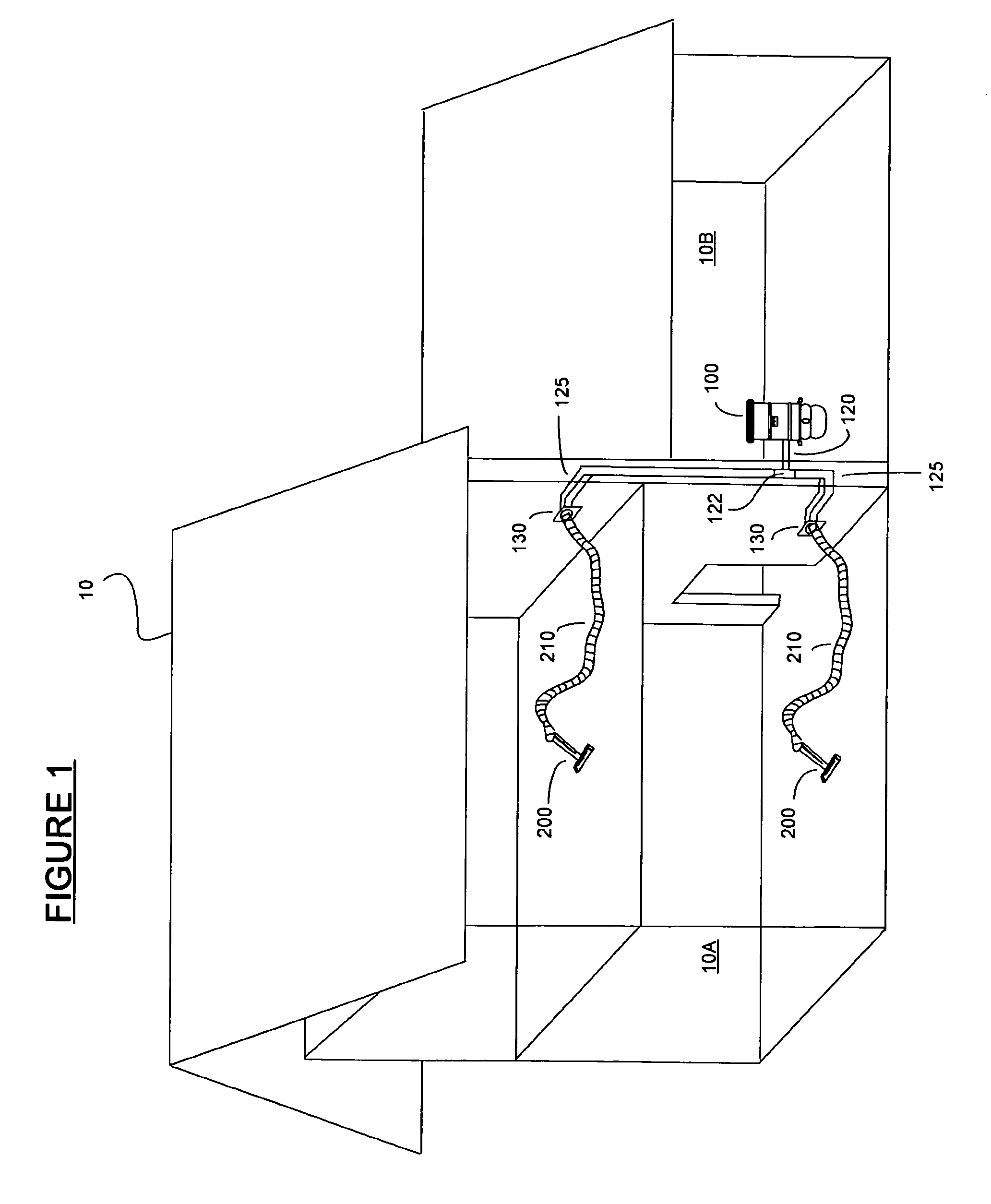
[0017]Referring now to FIG. 1, a schematic diagram of a residential structure employing a central vacuum cleaner system is illustrated. The residential structure 10 is a multilevel structure with a primary residential portion 10A and secondary portion 10B. The central vacuum cleaner of FIG. 1 comprises a power unit 100 located in t...


PUM


Abstract

A programmable control unit for a vacuum cleaning system, such as central vacuum cleaning system. A control unit is programmed after manufacture to execute a particular control program for performing various diagnostic and operational functions including user interface, voltage level detecting, voltage monitoring, current monitoring, user interface, power supply control, temperature monitoring, AC line frequency detection, operation data recording, speed control program selection, expansion bus interface and service tool interface. Power control to the vacuum motor is facilitated by the control unit directly through a triode for alternating current (TRIAC). Manufacturing costs are reduced by producing a single programmable control unit that can be programmed with a control program corresponding to a variety of different vacuum cleaning devices across a manufacturer's product line.

Description

FIELD OF THE INVENTION[0001]The present invention relates to vacuum cleaner systems and more particularly to a control system for central vacuum cleaner systems and other vacuum devices.BACKGROUND OF THE INVENTION[0002]Electric vacuum cleaning systems have become ubiquitous as the preferred method of cleaning carpeted and hard floors. These devices are manufactured in a variety of configurations including canister, upright, power wands, power heads, handhelds, etc. These different vacuum types differ in many design features such nozzle size and configuration, power agitation, cyclonic airflow and advanced dust filtering, however, they all share fundamental components. Vacuum cleaners typically include a handle portion attached to a cleaning nozzle / attachment, a dirt reservoir and a vacuum motor—that is, a motor and fan assembly that generates a working airflow from the nozzle to the dirt reservoir. Depending on the configuration all these items may be integrated into an upright or w...

Claims


Application Information

Patent Timeline
Patent Type & Authority Applications(United States)
IPC IPC(8): A47L5/38
CPCA47L5/38A47L9/2805A47L9/2842Y02B40/82A47L9/2889A47L9/2894A47L9/2857Y02B40/00
Inventor FOSTER, ALAN STIMSONKOESTNER, MITCHELL WAYNEKUBOVICH, MARK WILLIAMMEYER, TREVOR E.
Owner ELECTROLUX HOME CARE PRODS
Why Eureka
Try Eureka