Instrumented Tabular Device for Transporting a Pressurized Fluid

a tubular device and pressurized fluid technology, applied in the direction of optical conversion of sensor output, fluid removal, survey, etc., can solve the problems of cumulated stress and fatigue, significant cost, and scarce deposits

Inactive Publication Date: 2007-12-13
COMMISSARIAT A LENERGIE ATOMIQUE ET AUX ENERGIES ALTERNATIVES
View PDF12 Cites 115 Cited by
  • Summary
  • Abstract
  • Description
  • Claims
  • Application Information

AI Technical Summary

Problems solved by technology

In the field of oil exploration, deposits tend to become scarce.
Cumulated stresses and fatigue are therefore significant.
Such plugs, when they are formed, may lead to conduit blocking and result in significant costs.
The solutions of the prior art using electrical sensors (accelerometers, electrical strain gages, thermocouples) are not considered as being reliable as permanent measuring tools for temperatures exceeding 120° C. Their lifetimes are too short (operators presently demand an operating time guaranteed over 20 years).
Further, the cost for replacing such electrical sensors is high, because production standstill may be required in the case of the blocking of a conduit by a hydrate plug.
The measuring systems installed today require, because of their diversity, different associated networks for conveying t

Method used


Image

  • Instrumented Tabular Device for Transporting a Pressurized Fluid
  • Instrumented Tabular Device for Transporting a Pressurized Fluid
  • Instrumented Tabular Device for Transporting a Pressurized Fluid

Examples


first embodiment

of the Invention

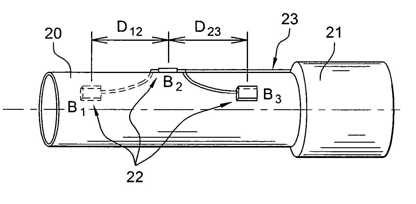
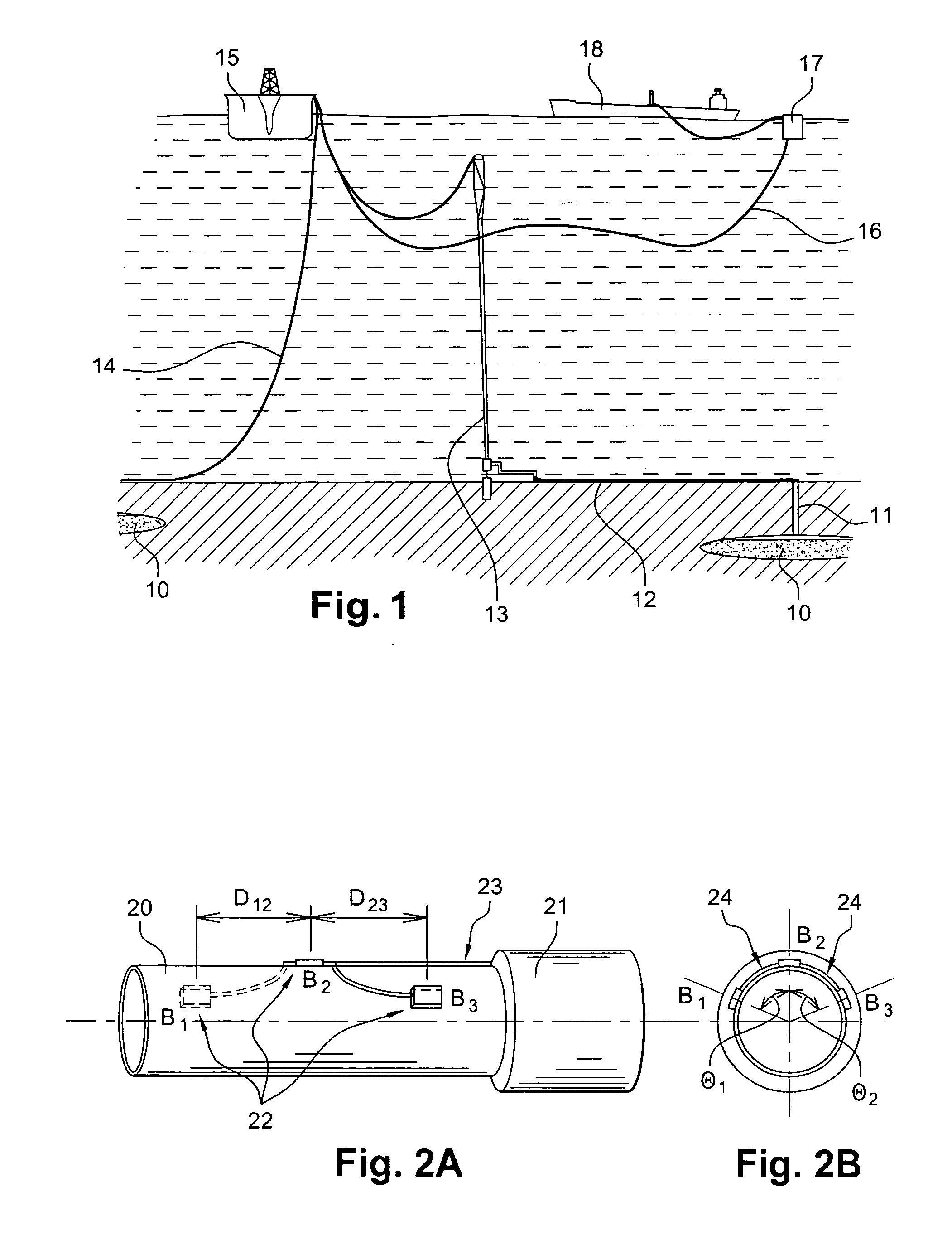
[0064] In this first embodiment, the three locations 22 are occupied by casings, in which three sensors insulated from the external hydrostatic pressure, are positioned respectively. Each instrumented portion of the device of the invention, illustrated in FIG. 2 after removing the heat insulator 21, comprises a preassembled assembly consisting of a least one central casing B2 and two side casings B1 and B3, preformed tubular connectors 24 (with the tube diameter) connecting the casings with each other and a remote optical fiber (or “offset” optical fiber) 23 connecting the central casing B2 to the measurement instrumentation located at the surface. The casings are installed along the axis of the tube (for example every decimeter) and according to different angular orientations. In the remote cable (or “offset” cable) leading to the instrumentation at the surface, a set of three casings therefore corresponds to one optical fiber.

[0065]FIG. 2B shows a distribution of ...

second embodiment

of the Invention

[0071] In this second embodiment, the device of the invention is instrumented with sensors located in locations similar to those of the first embodiment. This time, the sensors are directly adhered to the tube without protective casings against the external hydrostatic pressure. The sensors of a same instrumented portion of the device of the invention, or double-joint sensors, are connected to each other through a remote optical cable, which is connected to a main optical cable at a distribution box, positioned at the head of the instrumented portion. The sensors and the remote optical cable are embedded in a coating which seals them from the external medium, hermetically. The main optical cable connects the distribution box and the instrumentation located at the surface. This distribution box enables the seal of the main and remote optical cables to be guaranteed. The distribution of the optical fibers along the tube in multiple instrumented portions is provided in ...


PUM


Abstract

The invention relates to an instrumented tubular device for transporting a pressurized fluid notably in the field of oil exploration and in that of the transport of gas or hydrocarbons. This device comprises a tube (20) in which this fluid flows, with which are associated means for measuring the main deformations of this tube, and means for measuring the temperature of the fluid in the tube. This tube is equipped with measurement means integral with its surface and offset by at least one remote optical cable towards an electronic measurement system. These measurement means are means for assembling at least two non-parallel optical fibers which comprise at least three assemblies (B1, B2, B3) of at least two optical gages with Bragg gratings attached to at least three measurement locations (22) and connected to the remote optical cable (23) via optical fibers. At least one assembly further comprises a temperature gage.

Description

TECHNICAL FIELD [0001] The present invention relates to an instrumented tubular device for transferring a pressurized fluid, notably in the field of oil exploration, and in that for the transport of gas or hydrocarbons. STATE OF THE PRIOR ART [0002] In the field of oil exploration, deposits tend to become scarce. Exploitation of new deposits is carried out more and more frequently offshore, or even in the high seas and at great depths (deep offshore). In this context, real-time assistance to production services of offshore and deep offshore oil fields is a new need and specific to developments consecutive to such exploitation. [0003] With the objective of reducing bulkiness and costs, the tubes used operate close to their design limits. Cumulated stresses and fatigue are therefore significant. [0004] As illustrated in FIG. 1, the hydrocarbon fluid under pressure (typically 70 bars or more) and subject to a high temperature (typically 100° C. or more) is extracted from one or more re...

Claims


Application Information

Patent Timeline
IPC IPC(8): E21B47/06E21B17/00E21B43/01F17D5/00F17D5/06G01D5/353G01L1/24G01L11/02
CPCE21B43/01F17D5/06G01L11/025G01L1/246G01D5/35383
Inventor MAGNE, SYLVAINFERDINAND, PIERREDANIEL, PIERRE-JEAN
Owner COMMISSARIAT A LENERGIE ATOMIQUE ET AUX ENERGIES ALTERNATIVES
Why Eureka
Try Eureka