Vehicle Hydraulic Regenerative System

Inactive Publication Date: 2007-12-13
PATTERSON RICKIE W
View PDF25 Cites 14 Cited by
  • Summary
  • Abstract
  • Description
  • Claims
  • Application Information

AI Technical Summary

Benefits of technology

[0012]An object of the present invention is to enhance electric vehicle operating range by providing a regenera

Problems solved by technology

While the environmental benefits of electric vehicle usage are generally accepted and sought after in modern society, the technology has not yet provided solutions enabling electric vehicles to rival those powered by internal combustion engines in travel range and performance other performance characteristics.
However, such systems are typically limited to providing regenerative power during vehicle braking or deceleration.
One of the recognized problems in regenerative technologies is electric motor inefficiency over a wide range of vehicle operating parameters.
While motor selection in many static applications can be readily ach

Method used


Image

  • Vehicle Hydraulic Regenerative System
  • Vehicle Hydraulic Regenerative System
  • Vehicle Hydraulic Regenerative System

Examples


Example

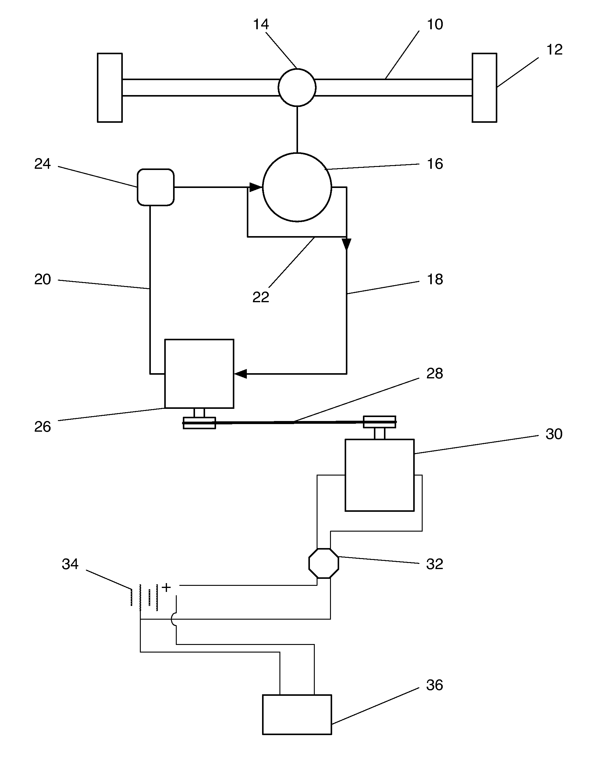
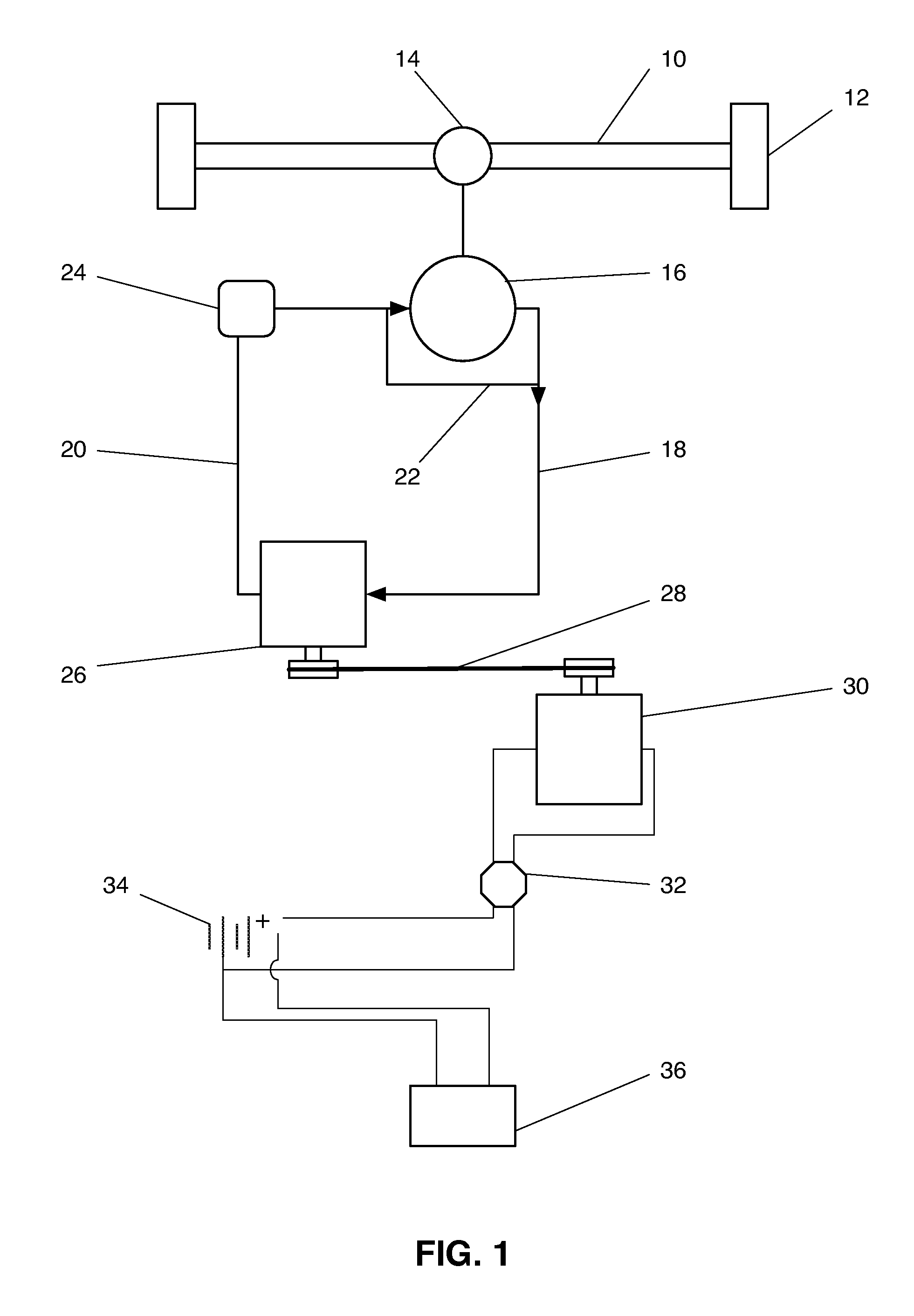
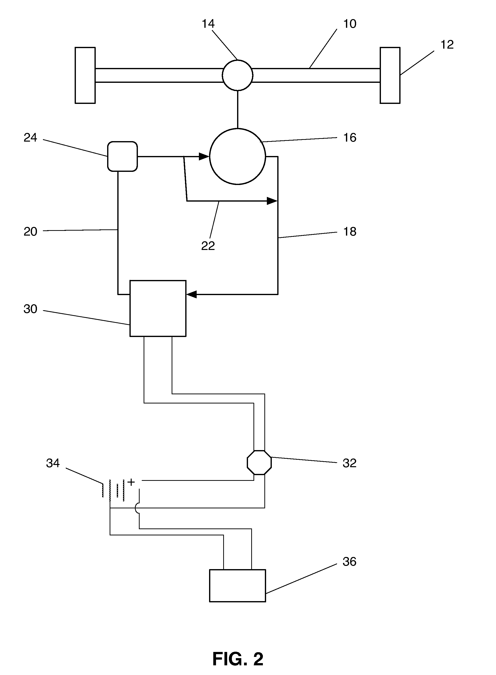
[0024]FIG. 1 depicts a vehicle axle 10 having two tires 12 and a geared differential 14 affixed thereto. The axle 10 is preferably a non-drive axle 10. A connecting means connects a hydraulic pump 16 to the differential 14 so that tire 12 and axle 10 rotation powers the hydraulic pump 16. A hydraulic circuit comprised of a supply line 18 and return line 20 provides fluid communication between the hydraulic pump 16 and a hydraulic motor 26. The circuit further comprises a hydraulic fluid reservoir 24 for retaining proper levels of hydraulic fluid during operation. A pressure bypass line 22 having a flow control valve provides fluid communication between the supply line 18 and return line 20 so that pressure levels are maintained between the supply and return line 20 during operation. Pressurized hydraulic fluid powers the hydraulic motor 26 as the hydraulic fluid moves through the hydraulic circuit under power form the hydraulic pump 16.

[0025]A connecting means, such as a tensioned p...


PUM


Abstract

A regenerative system for a recharging vehicle batteries utilizing a hydraulic circuit having a hydraulic pump linked to a non-drive axle powering the pump, the pump providing power to at least one hydraulic generator so that the generator operates continuously within optimum operating parameters once the vehicle travels at or above a predetermined speed.

Description

BACKGROUND OF THE INVENTION[0001]1. Field of Invention[0002]This invention relates to regenerative energy systems for vehicles. More particularly, this invention relates to a hydraulically driven, constant output, regenerative drive system by converting non-drive axle rotational energy into electric energy.[0003]2. Description of the Related Art[0004]Extensive efforts to increase utilization of electric vehicles have been made over the last few decades. While the environmental benefits of electric vehicle usage are generally accepted and sought after in modern society, the technology has not yet provided solutions enabling electric vehicles to rival those powered by internal combustion engines in travel range and performance other performance characteristics.[0005]Prior systems and devices take various approaches to solving the problems of electric vehicle operational performance. Improvements in battery technology, motor technology, and regenerative technology, among others, contin...

Claims


Application Information

Patent Timeline
IPC IPC(8): B60L8/00B60K17/00
CPCB60K1/00B60L2200/26B60L7/10Y02T10/7072
Inventor PATTERSON, RICKIE W.
Owner PATTERSON RICKIE W
Why Eureka
Try Eureka