Gas concentration measuring apparatus designed to enhance measurement accuracy in desired range

a technology of gas concentration and measuring apparatus, applied in the direction of instruments, material electrochemical variables, electric control, etc., can solve problems such as the change in the resolution of the measurement of gas concentration

Active Publication Date: 2007-12-13
DENSO CORP
View PDF7 Cites 11 Cited by
  • Summary
  • Abstract
  • Description
  • Claims
  • Application Information

AI Technical Summary

Benefits of technology

[0016]The wide range may be defined to include at least one of an atmospheric air-equivalent value when the internal combustion engine is undergoing a fuel cut and a value of an air-fuel ratio during rich air-fuel ratio burning of the internal combustion en

Problems solved by technology

This results in a change in resolution of m

Method used


Image

  • Gas concentration measuring apparatus designed to enhance measurement accuracy in desired range
  • Gas concentration measuring apparatus designed to enhance measurement accuracy in desired range
  • Gas concentration measuring apparatus designed to enhance measurement accuracy in desired range

Examples


first embodiment

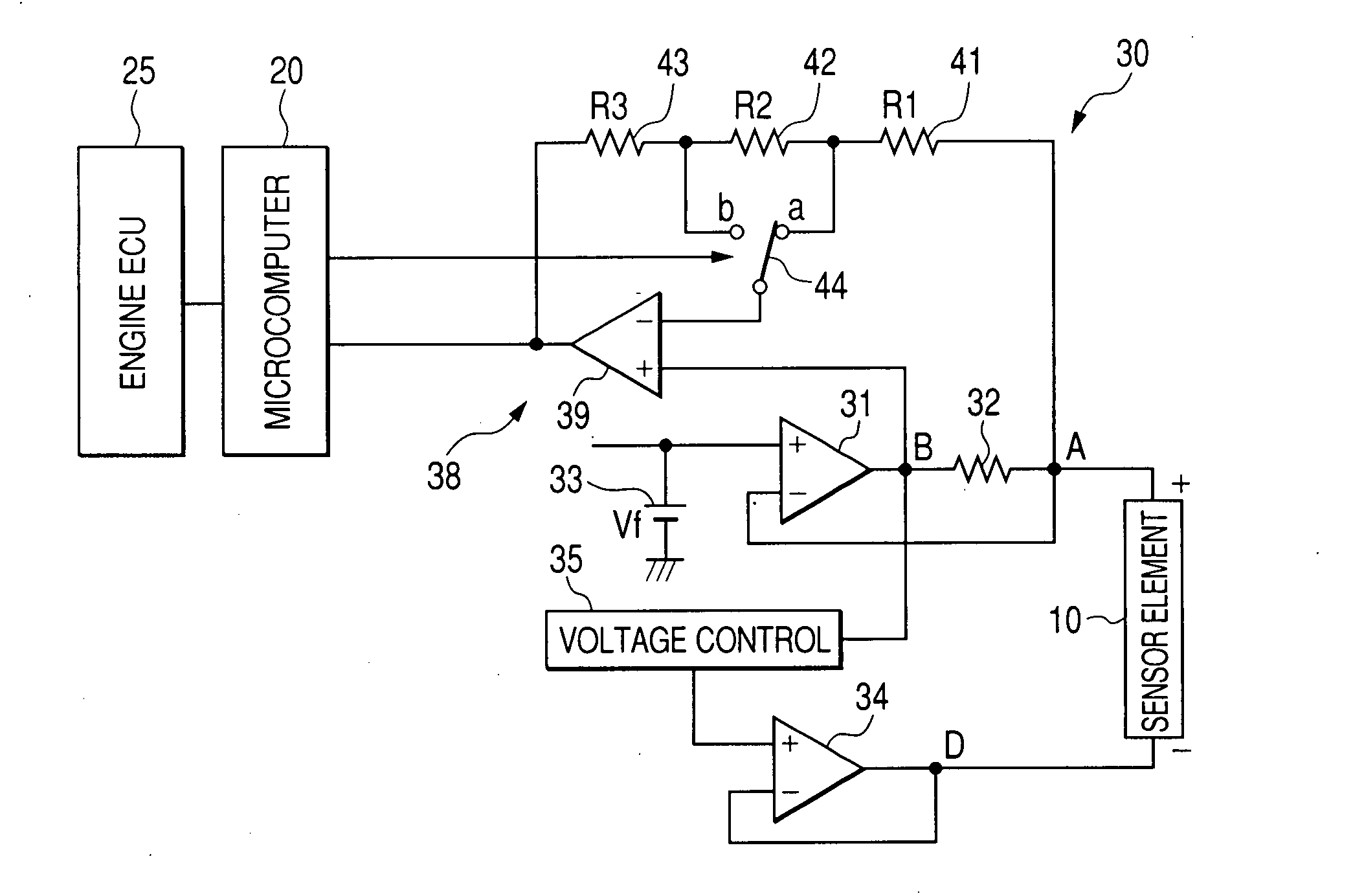
[0065]The amplifier circuit 38 connects with the junctions D and E leading to the ends of the current-measuring resistor 32. The A / F output voltage that is an output of the amplifier circuit 38 is inputted to the A / D converter of the microcomputer 20. The amplifier circuit 38 is made up of the operational amplifier 39, the series-connected amplifying resistors 41, 42, and 43, and the switch 44 made of, for example, a MOS transistor. Specifically, the amplifier circuit 38 has the same structure as the one in FIG. 1. The switch 44, like the first embodiment, works to establish the electrical connection of the operational amplifier 39 with the contact a or b selectively to change the amplification factor of the amplifier circuit 38 between the higher and lower one. When the switch 44 establishes, as illustrated in the drawing, the electrical connection between the operational amplifier 39 and the contact a, the amplifier circuit 38 has the amplification factor GA, as represented by equ...

fifth embodiment

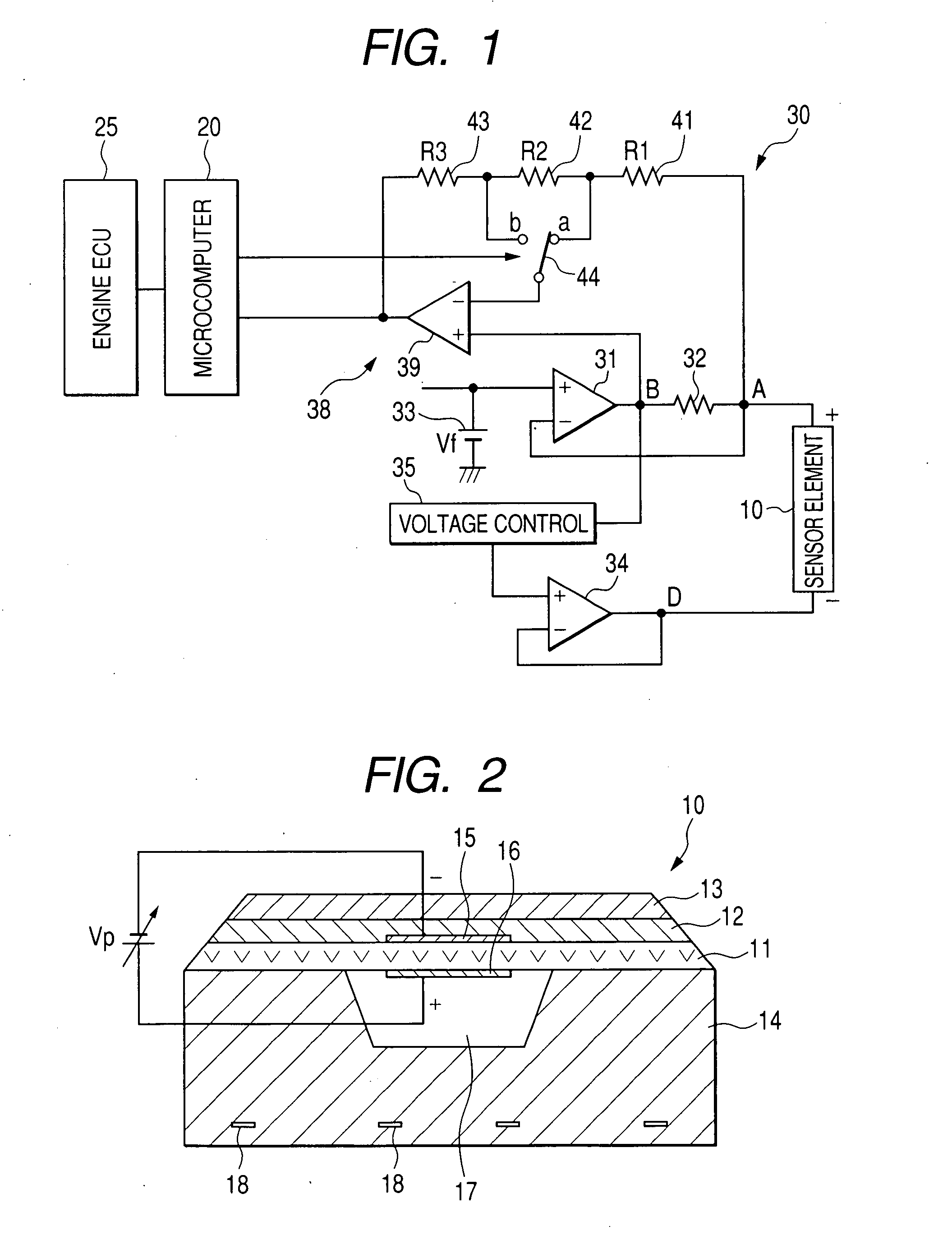
[0084]FIG. 8(b) shows a sensor element 80 according to the invention which may be built in the A / F sensor, as employed in each of the above embodiments.

[0085]The sensor element 100 includes three solid electrolyte layers 81, 82, and 83. The solid electrolyte layer 81 has electrodes 84 and 85 affixed to opposed surfaces thereof. Similarly, the solid electrolyte layer 82 has electrodes 86 and 87 affixed to opposed surfaces thereof. The solid electrolyte layer 81 and the electrodes 84 and 85 form a pump cell 91. The solid electrolyte layer 82 and the electrodes 86 and 87 form an oxygen sensor cell 91. The solid electrolyte layer 83 forms a wall defining an oxygen reference chamber 88. The sensor element 80 is, like the sensor element 10, of a laminated structure. The sensor element 80 also includes a porous diffusion layer 89 and a gas chamber 90 into which exhaust gas of the automotive engine enter. The oxygen sensor cell 92 operates, like the oxygen sensor cell 72 illustrated in FIG....


PUM


Abstract

A gas concentration measuring apparatus for use in air-fuel ratio control of automotive engines is designed to determine the concentration of oxygen within a wide and a narrow range using a sensor current flowing through a sensor element. The apparatus includes an amplifier circuit equipped with an operational amplifier and a plurality of amplifying resistors and a switch. The switch is responsive to a request signal to switch a relation in electrical connection between an operational amplifier and the amplifying resistors to distribute the amplifying resistors into an input resistor and a feedback resistor for the operational amplifier to change an amplification factor of the amplifier circuit. This results in a change in resolution of measurement of the concentration of oxygen, thereby ensuring enhanced accuracy in determining the concentration of oxygen in a selected one of the narrow and wide ranges.

Description

CROSS REFERENCE TO RELATED DOCUMENT[0001]The present application claims the benefit of Japanese Patent Application No. 2006-146392 filed on May 26, 2006 the disclosures of which are incorporated herein by reference.BACKGROUND OF THE INVENTION[0002]1. Technical Field of the Invention[0003]The invention relates generally to a gas concentration measuring apparatus which may be used in measuring the concentration of a preselected component, such as oxygen, of exhaust emissions of automotive engines, and more particularly to such a gas concentration measuring apparatus designed to ensure enhanced accuracy in determining the concentration of gas in a desired measuring range.[0004]2. Background Art[0005]There are known gas concentration measuring apparatuses designed as air-fuel ratio measuring apparatuses to measure the concentration of oxygen (O2) contained in exhaust gas emitted from an automotive engine to determine an air-fuel ratio of a mixture charged into the engine for use in air-...

Claims


Application Information

Patent Timeline
IPC IPC(8): G01N27/26
CPCF02D41/1454G01N27/419F02D41/28G01R1/203G01R19/0092G01R15/08
Inventor KAWASE, TOMOOKUROKAWA, EIICHIHADA, SATOSHISUZUKI, TOSHIYUKIAKIMOTO, KATSUHIDE
Owner DENSO CORP
Why Eureka
Try Eureka