Adaptive multi-beam system

a multi-beam antenna and antenna technology, applied in the field of wireless communication, can solve the problems of reducing the capital cost of installing base stations, not meeting the potential capacity discussed above, and not meeting the maximum reach of cell phones,

Inactive Publication Date: 2007-12-13
TENXC WIRELESS
View PDF8 Cites 96 Cited by
  • Summary
  • Abstract
  • Description
  • Claims
  • Application Information

AI Technical Summary

Benefits of technology

[0085] Further, the present invention provides robust methods of distinguishing a desired signal from a strong interfering signal.

Problems solved by technology

In such a case, the potential capacity discussed above is not achieved because the total number of slots must be shared between the uplink and downlink directions.
Thus, the cell size (or the coverage area) is limited not only by the maximum reach, but also by the angular spacing.
Sectorization not only increases the capacity by decreasing interference, but it also decreases the capital cost of installing base stations, as a particular antenna site could house a plurality of outward facing sectors.
However, higher sectorization may be challenging for previously known communications systems because there is only limited room for change.
With higher sectorization, the number of users being in a handover situation between sectors, and thus the overhead cost, also increases because the sectors are narrower.
Therefore, when this upper limit is reached or approached, the options remaining for further increasing user capacity are limited.
These, unfortunately, are uncorrelated with the parameters in the downlink direction.
Nevertheless, others of the available uplink channel parameters may not be different for the downlink across a short time interval.
Unfortunately, it is well known that the state of the art methods of so doing suffer from lack of robustness.
Accordingly, any error in the calibration of the antenna array or any motion on the part of a co-channel interferer will translate in an undesired shift of a null location.
Provided, however, that the undesired angular shift remains small, the degradation in the beamforming performance may not be significant.
As such, the signals on the beams would be highly correlated and it is relatively challenging to discriminate between desired weak and strong noise signals.
In particular, for a specific geographic location of the mobile transmitter within a sector, it is unlikely that a single beam will capture all of the dominant components of the received signal.
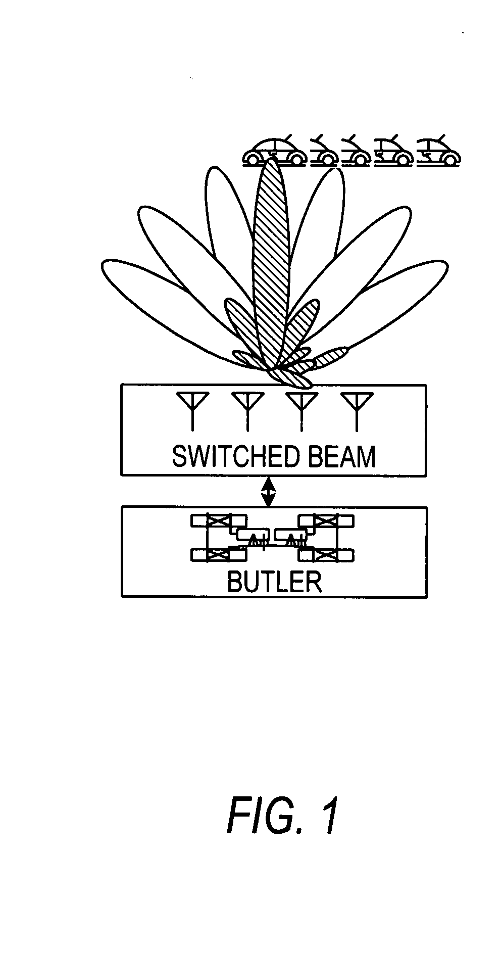
Unfortunately, typical switched beam systems only consider a single beam to process a desired signal.
Accordingly, the attendant simplification of design of such systems results in a degradation of the system performance.
Further, beam selection based solely on power measurements, as in the switched beam systems, may not be satisfactory because it is possible that one locks onto a strong interfering signal rather than the desired user signal.
One could compensate for such loss by power control, but the transmission of excess power may cause corresponding interference to other cells in the network.
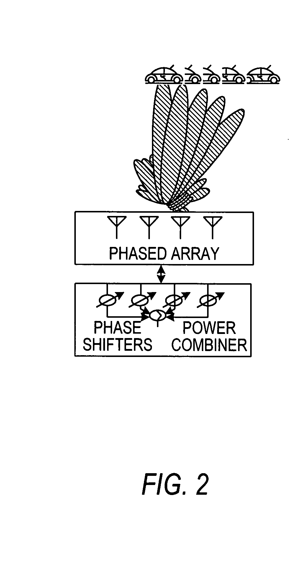
As well, by applying non-uniform weighting on the antenna array columns, the width of the steered beam may be varied as well.
However, null steering uses some intelligence about the direction of the desired and interfering signals.
Although in theory, null steering offers an optimal SINR, it may nevertheless not provide an optimal or even the most practical implementation for systems complying with existing wireless communications standards.
Moreover, the complexity of null steering systems may render them unaffordable when applied to all of the active subscribers in a cellular sector.
In the case of GSM systems, existing features such as slow frequency hopping (SFH) and discontinuous transmission (DTX) may similarly dramatically complicate an implementation of a null steering system.
Under slow frequency hopping conditions, there is no simple means of detecting interfering signal directions, because the downlink direction precedes the uplink direction and changes as to which signals will be interfering will occur for each frame.
Under discontinuous transmission conditions, only limited information will be available to estimate the DoA of the desired and interfering signals.
This limited information may be insufficient to derive proper null steering algorithms.
The problem would be considerably exacerbated if slow frequency hopping is also deployed.
If, however, one were to map antenna signals into a reduced number of beam signals, and work in beam space rather than element space, a constraint arises, namely that the number of transceivers would be multiplied by the number of narrow beams.
However, when the number of transceivers is very high, multiplying this number by the number of beam nodes would result in an unacceptably large number of RF feeders, and ancillary equipment.

Method used


Image

  • Adaptive multi-beam system
  • Adaptive multi-beam system
  • Adaptive multi-beam system

Examples


Embodiment Construction

[0103] The invention will be described for the purposes of illustration only in connection with certain embodiments; however, it is to be understood that other objects and advantages of the present invention will be made apparent by the following description of the drawings according to the present invention. While a preferred embodiment is disclosed, this is not intended to be limiting. Rather, the general principles set forth herein are considered to be merely illustrative of the scope of the present invention and it is to be further understood that numerous changes may be made without straying from the scope of the present invention.

[0104]FIGS. 1, 2, and 3 are schematic diagrams of a switched beam beamforming network array, a phased-array beamforming network, and an adaptive null-steering beamforming network of the prior art which have been described above.

[0105] Referring now to FIG. 4, there is shown a high-level block diagram of an exemplary embodiment of a wideband appliqué...


PUM


Abstract

A system and method of providing an adaptive multi-beam capability to a wireless base transceiver station is disclosed. The system comprises a plurality of transmit and receive antenna arrays and a plurality of static beamformers to form a limited number of beams. The beam data is reduced to digital baseband form whereupon it is digitally beamformed using a set of adaptive beamforming weights generated having regard to the form and content of the data and the environment. Such form and content information is obtained directly or indirectly from the base transceiver station. The weights are calculated using an average power function derived from a correlation of the beam data with a reference signal that mimics the training sequence assigned to the base transceiver station. Because the average power does not vary widely from frame to frame, the weights derived from the uplink direction may be reapplied in the downlink direction. Specific provision is made for data packets, where downlink packets may contain control information intended for broadcast to all subscribers.

Description

CROSS REFERENCE TO RELATED APPLICATIONS [0001] This application claims the benefit of Canadian Patent Application No. 2,542,445 filed Apr. 7, 2006, which disclosure is incorporated herein by reference in its entirety. BACKGROUND TO THE INVENTION [0002] 1. Field of the Invention [0003] The present invention relates to wireless communications and in particular to an adaptive multi-beam antenna system. [0004] 2. Description of the Prior Art [0005] In wireless communication systems, the frequency spectrum is a scarce resource that must be used efficiently. [0006] One idea for increasing capacity in the face of this resource constraint was to divide a geographic area into smaller regions or cells, and to restrict each cell to a limited number of channels. Depending upon the access technique employed in the system, frequency channels may or may not be re-used in adjacent cells. [0007] For frequency division multiple access (FDMA) systems, such as the GSM standard, it is preferred that adj...

Claims


Application Information

Patent Timeline
Patent Type & Authority Applications(United States)
IPC IPC(8): H04B7/26
CPCH01Q1/246H01Q3/24H04B7/0857H04B7/0617H01Q3/40
Inventor GAO, SHIWEITRIGUI, HAFEDH
Owner TENXC WIRELESS
Why Eureka
Try Eureka