Image coding apparatus and image coding method

a technology of image coding and coding apparatus, which is applied in the field of image coding apparatuses and image coding methods, can solve the problems of enormous amounts of arithmetic processing for coding, and achieve the effect of reducing arithmetic processing and high compression ratio

Active Publication Date: 2007-12-13
MAXELL HLDG LTD
View PDF19 Cites 54 Cited by
  • Summary
  • Abstract
  • Description
  • Claims
  • Application Information

AI Technical Summary

Benefits of technology

[0012]The present invention provides an image coding apparatus and an image coding method for reducing arithmetic processing while keeping a high compression ratio.
[0014]According to the present invention, it is possible to provide an image coding apparatus and an image coding method for reducing arithmetic processing while keeping a high compression ratio.

Problems solved by technology

74-90, (November, 1998), coding / decoding processes such as calculation of a prediction error, DCT transform, quantization, calculation of generating coding amounts, inverse quantization, inverse DCT transform, and calculation of distortion amounts are necessary to be performed for each coding mode and each block size, which results in enormous amounts of arithmetic processing for coding.

Method used


Image

  • Image coding apparatus and image coding method
  • Image coding apparatus and image coding method
  • Image coding apparatus and image coding method

Examples


first embodiment

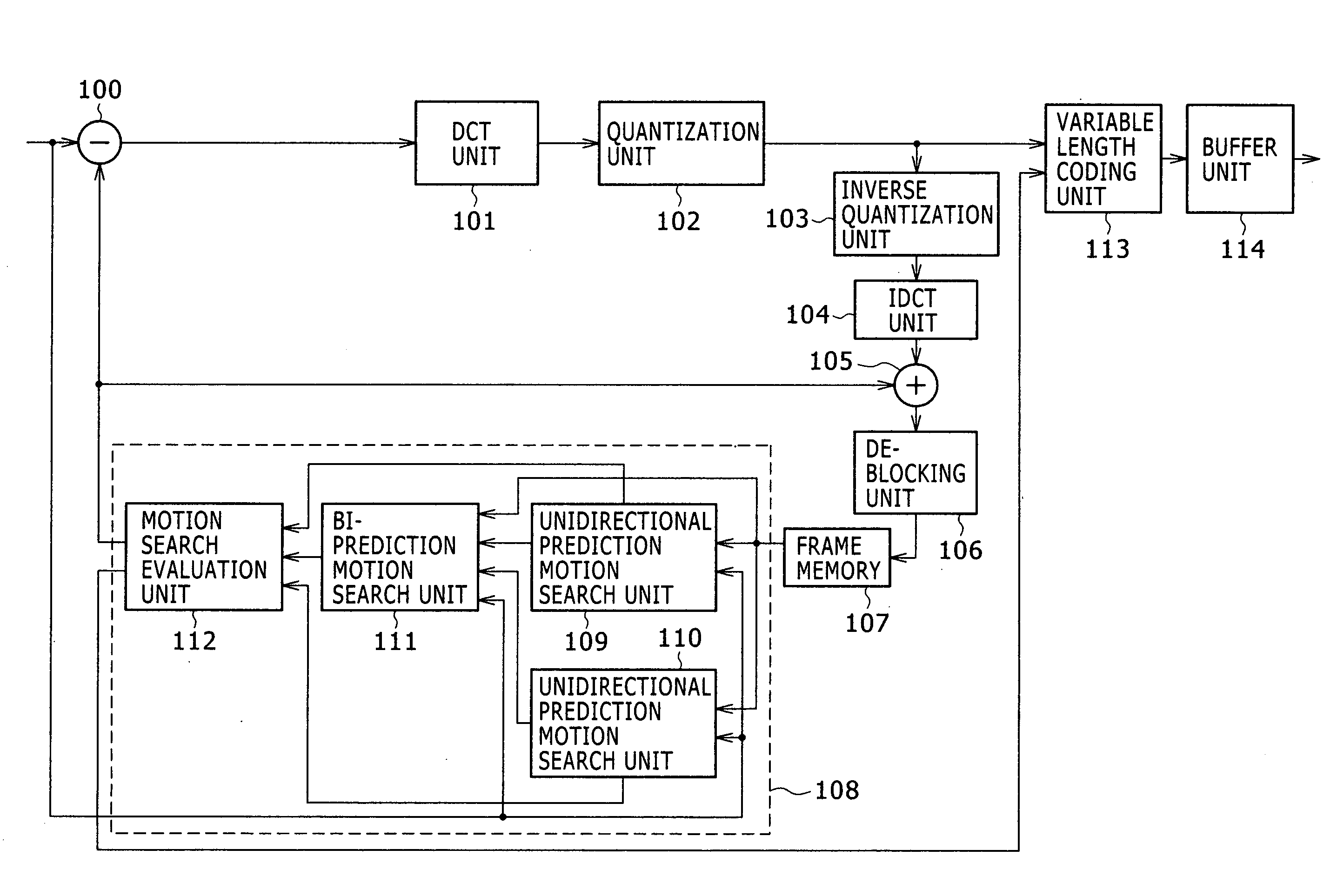
[0045]FIG. 1 is a configuration block diagram of an image coding apparatus according to a first embodiment of the present invention. The image coding apparatus shown in FIG. 1 includes a subtractor (100), a DCT unit (101), a quantization unit (102), an inverse quantization unit (103), an IDCT unit (104), an adder (105), a deblocking unit (106), a frame memory (107), a motion search / evaluation unit (108), a variable length coding unit (113), and a buffer unit (114). Among these units, the motion search / evaluation unit (108) includes unidirectional prediction motion search units (109) and (110), a bi-prediction motion search unit (111), and a motion search evaluation unit (112). The respective units may be constituted by hardware or software. Alternatively, the respective units may be modules obtained by combining hardware and software. As for the respective units in FIG. 1, blocks given the same numerals as those in the conventional image coding apparatus shown in FIG. 10 have the sa...

second embodiment

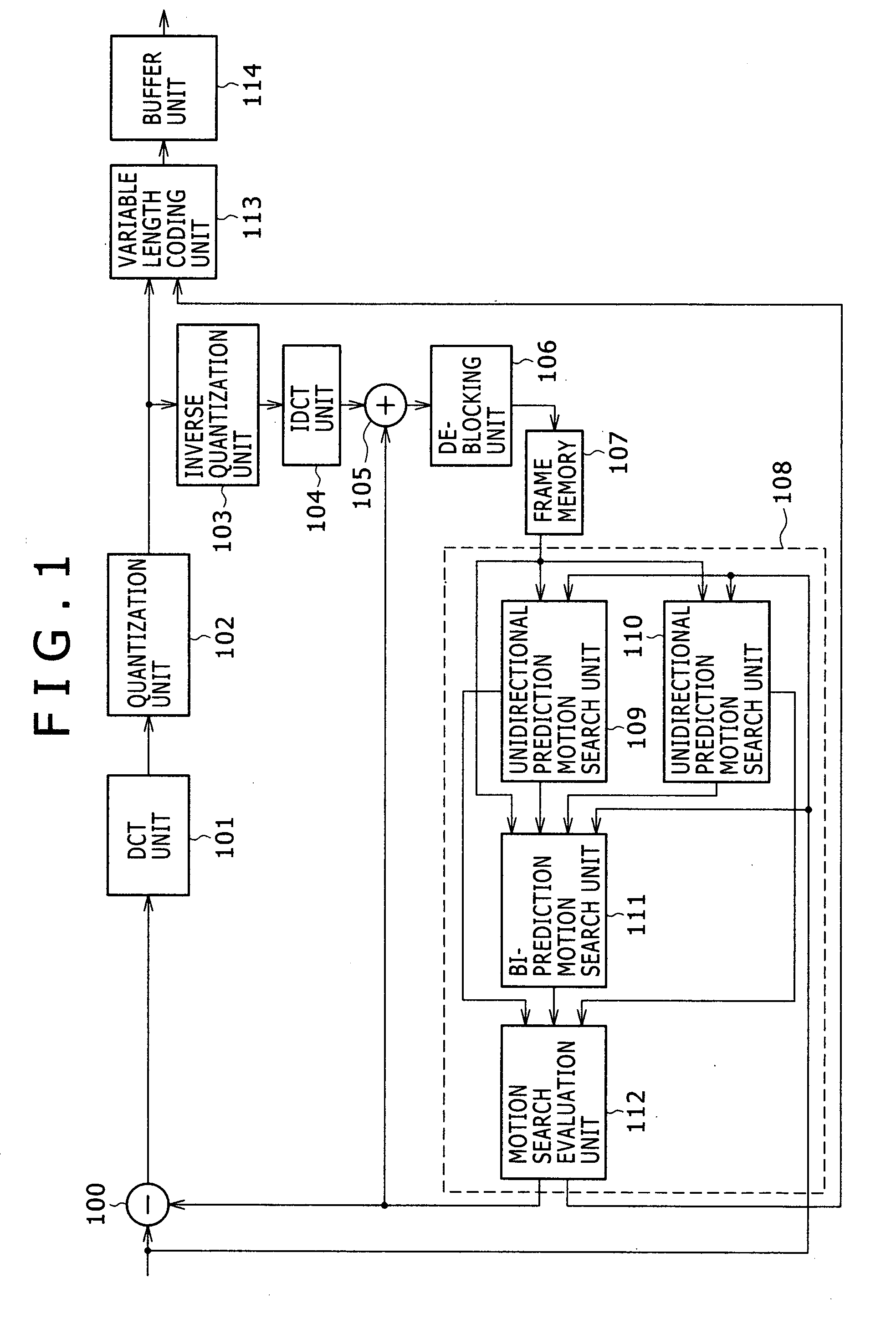
[0052]Next, a second embodiment of the present invention will be described. A configuration block diagram of an image coding apparatus according to the second embodiment of the present invention is the same as that of FIG. 1 in the first embodiment, and therefore the explanation thereof is omitted. Hereinafter, an operation of the motion search / evaluation unit (108) will be described with reference to FIG. 3. The unidirectional prediction motion search units (200) and (210), and the motion search evaluation unit (230) in FIG. 3 are the same as those in FIG. 2, and therefore the explanation thereof is omitted. In the bi-prediction motion search unit (220), a bi-prediction motion search block size setting unit (224) determines a block size by which a bi-prediction search is performed from block sizes notified by the unidirectional prediction motion search unit (200) and the unidirectional prediction motion search unit (210). A motion search unit (225) performs a bi-prediction motion s...

third embodiment

[0059]Next, a third embodiment of the present invention will be described. A configuration block diagram of an image coding apparatus according to the third embodiment of the present invention is the same as that of FIG. 1 in the first embodiment, and therefore the explanation thereof is omitted. Hereinafter, an operation of the motion search / evaluation unit (108) will be described with reference to FIG. 5. The unidirectional prediction motion search units (200) and (210), and the motion search evaluation unit (230) in FIG. 5 are the same as those in FIG. 2, and therefore the explanation thereof is omitted. In the bi-prediction motion search unit (220), a bi-prediction motion search center setting unit (241) sets a search center in a motion search within a reference picture to which the reference image block A belongs when performing a bi-prediction motion search, on the basis of a motion vector selected by the unidirectional prediction motion search unit (200) where the reference i...


PUM


Abstract

The present invention provides an image coding apparatus and an image coding method for reducing arithmetic processing while keeping a high compression ratio. A coding process necessary for the bi-prediction motion search can be effectively reduced by determining a block size for a bi-prediction motion search or a center position for a motion search on the basis of a result of a motion search of a unidirectional prediction. Further, a compression ratio can be also kept as high as possible, because the block size or the center position are obtained on the basis of the result of the motion search of the unidirectional prediction.

Description

CLAIM OF PRIORITY[0001]The present application claims priority from Japanese application serial no. JP 2006-159231, filed on Jun. 8, 2006, the content of which is hereby incorporated by reference into this application.BACKGROUND OF THE INVENTION[0002](1) Field of the Invention[0003]The present invention relates to image coding apparatuses and image coding methods by which a moving image is coded with high efficiency, and particularly to motion compensation inter prediction coding in which coding is performed using temporally-previous and temporally-subsequent images.[0004](2) Description of the Related Art[0005]As a technique for coding moving image data such as TV signals with high efficiency for recording or transmission, a coding system such as the MPEG (Moving Picture Experts Group) system has been designed, and is an international-standard coding system as the MPEG-1 standard, the MPEG-2 standard, and MPEG-4 standard. Further, as a system of further improving a compression rati...

Claims


Application Information

Patent Timeline
Patent Type & Authority Applications(United States)
IPC IPC(8): H04N7/28H04N19/50H03M7/36H04N19/105H04N19/119H04N19/127H04N19/136H04N19/137H04N19/139H04N19/147H04N19/159H04N19/174H04N19/176H04N19/19H04N19/503H04N19/51H04N19/573H04N19/61H04N19/625H04N19/91
CPCH04N19/51H04N19/577H04N19/57H04N19/53
Inventor ITO, HIROAKIMURAKAMI, TOMOKAZUKARUBE, ISAONAKAMURA, TAKUYATABE, YUSUKE
Owner MAXELL HLDG LTD
Why Eureka
Try Eureka