
Timing-aware test generation and fault simulation

a technology of timing awareness and test pattern, applied in the direction of error detection/correction, design optimisation/simulation, instruments, etc., can solve the problems of circuits that are typically affected by delay-related defects, and circuits that are more susceptible to timing-related defects, so as to improve the quality of a test set and improve the path coverage

Active Publication Date: 2007-12-13
SIEMENS PROD LIFECYCLE MANAGEMENT SOFTWARE INC
View PDF15 Cites 59 Cited by
  • Summary
  • Abstract
  • Description
  • Claims
  • Application Information

AI Technical Summary

Benefits of technology

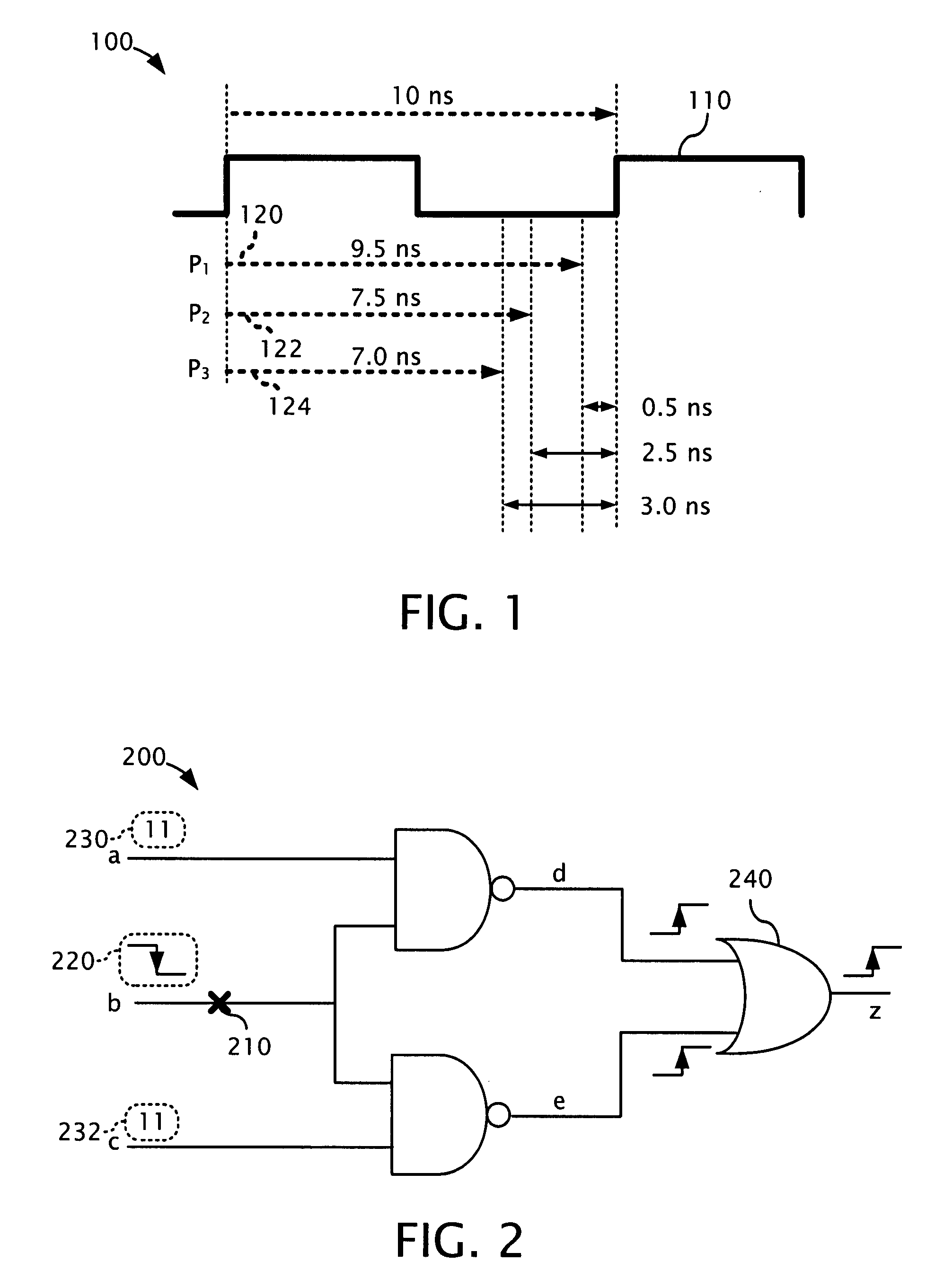
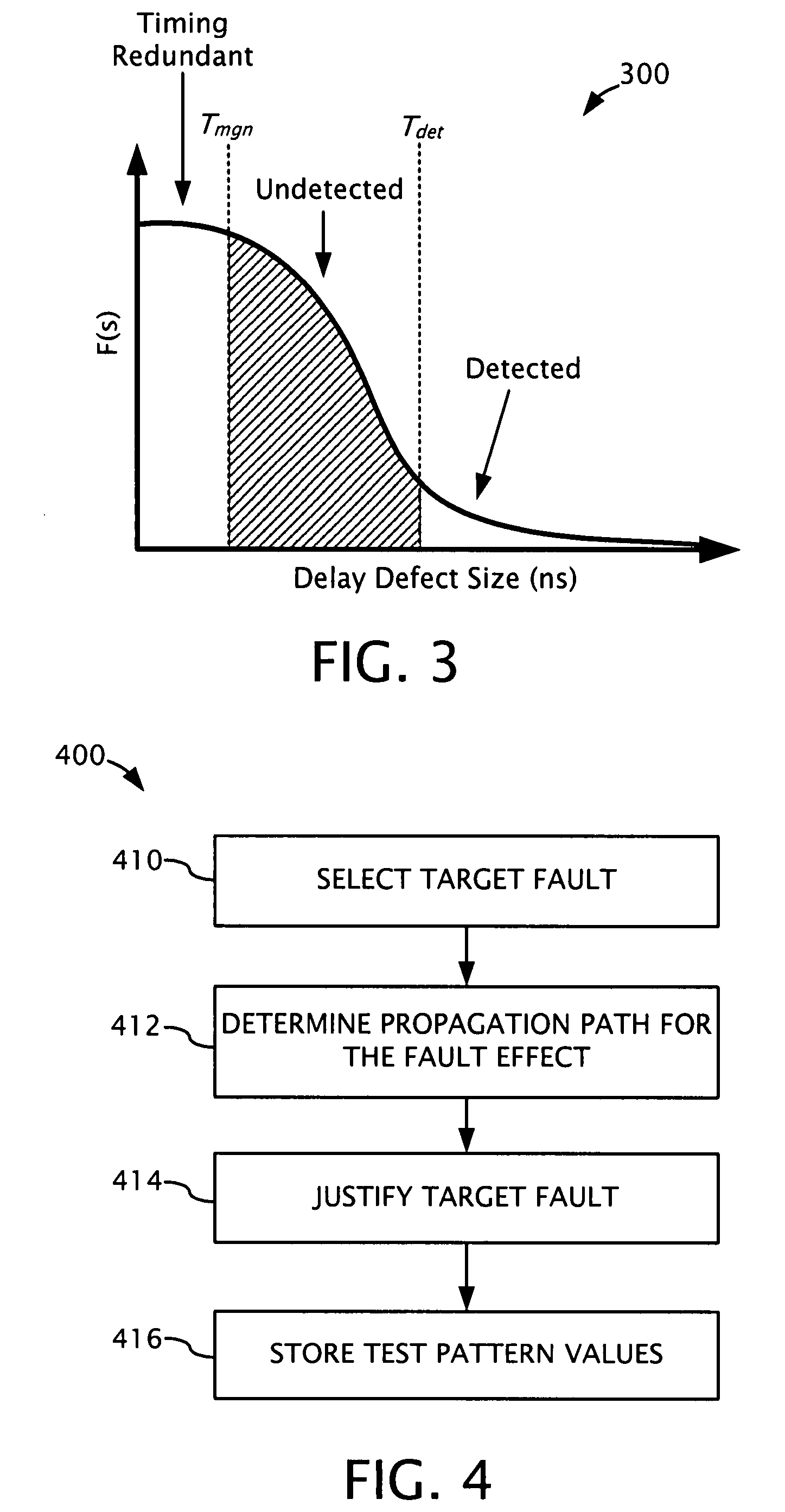
[0007] Disclosed herein are exemplary methods, apparatus, and systems for performing timing-aware automatic test pattern generation (ATPG) that can be used, for example, to improve the quality of a test set generated for detecting delay defects. In certain embodiments, timing information derived from various sources (e.g. from Standard Delay Format (SDF) files) is integrated into an ATPG tool. The timing information can be used to guide the test generator to detect the faults through certain paths (e.g., paths having a selected length, or range of lengths, such as the longest paths). To avoid propagating the faults through similar paths repeatedly, a weighted random method can be used to improve the path coverage during test generation. Experimental results show that significant test quality improvement can be achieved when applying embodiments of timing-aware ATPG to industrial designs.
[0012] A test generation method that detects small delay defects by launching a delay fault (e.g., a transition fault) through one of the sensitizable paths to the faulty site selected by using a weighted random justification decision, and propagating the fault from the faulty site to one of the sensitizable observation points selected by using a weighted random propagation decision. In certain embodiments, the weighted justification decision depends on the static arrival time of a gate input, such that the input with the longer arrival time contains a larger weight and has a higher probability of being selected as part of the justification path. In some embodiments, the weighted propagation decision can depend on the static propagation time of the gate fanout, such that the fanout gate with the longer propagation time contains a larger weight and has a higher probability of being selected as part of the propagation path.

Problems solved by technology

As logic circuits operate at higher frequencies and as feature sizes shrink, manufactured circuits become more vulnerable to timing-related defects.
Delay-related defects typically originate from process variations and random defects.
Process variations are ordinarily caused by physical parameter variations during the manufacturing process and usually cannot be completely eliminated.
Random delay defects, caused for example by resistive shorts and resistive vias, introduce additional delays and may also cause circuits to malfunction during normal operation.
The transition fault model, for instance, considers a gross delay at every gate terminal in the circuit and assumes that the additional delay at the fault site is large enough to cause a logic failure.
However, transition fault test generation generally ignores the actual delays through the fault activation and propagation paths, and is more likely to detect a fault through a shorter path.
As a result, the generated test set may not be capable of detecting small delay defects.

Method used


Image

  • Timing-aware test generation and fault simulation
  • Timing-aware test generation and fault simulation
  • Timing-aware test generation and fault simulation

Examples


exemplary embodiment 1100

[0114]FIG. 11 is a flowchart of an exemplary embodiment 1100 for applying the fault dropping criterion. At 1110, fault simulation is performed for a test pattern to determine the actual path delays. For example, the fault simulation procedure 900 illustrated in FIG. 9 can be performed for a test pattern ti. At 1112, a fault detected by the test pattern ti is selected. For example, one of the faults that was determined to be detected by the test pattern ti (e.g., at 912) can be selected. At 1114, a determination is made as to whether the fault should be removed from the fault list based at least in part on the actual slack of the path. For example, a criteria based on the slack margin (such as the criteria in expression (14)) can be used. Based on the outcome of the determination at 1114, the fault is either removed at 1116 or left remaining on the fault list. At 1118, a determination is made as to whether any faults remain on the fault list that were detected by the test pattern ti....

exemplary embodiment 1600

[0131]FIG. 16 is a flowchart of an exemplary embodiment 1600 for performing test pattern generation using the existence of timing critical faults as an additional criterion. At 1610, the target fault list is generated. At 1612, timing critical faults are identified from the target fault list. For example, in one desirable embodiment, timing critical faults are identified using the criterion shown in expression (16). At 1614, a fault from the target fault list is selected (e.g., the next fault) and is targeted at 1616 by the timing-aware deterministic test generation procedure. For instance, the test generation procedure 400 illustrated in FIG. 4 can be performed to generate a test pattern ti detecting the target fault. To simplify the test generation process and improve the chance of detecting the non-timing-critical faults, the timing-aware deterministic test generation procedure can be used for all explicitly target faults in this exemplary embodiment. At 1618, fault simulation is...


PUM


Abstract

Disclosed herein are exemplary methods, apparatus, and systems for performing timing-aware automatic test pattern generation (ATPG) that can be used, for example, to improve the quality of a test set generated for detecting delay defects or holding time defects. In certain embodiments, timing information derived from various sources (e.g. from Standard Delay Format (SDF) files) is integrated into an ATPG tool. The timing information can be used to guide the test generator to detect the faults through certain paths (e.g., paths having a selected length, or range of lengths, such as the longest or shortest paths). To avoid propagating the faults through similar paths repeatedly, a weighted random method can be used to improve the path coverage during test generation. Experimental results show that significant test quality improvement can be achieved when applying embodiments of timing-aware ATPG to industrial designs.

Description

CROSS-REFERENCE TO RELATED APPLICATIONS [0001] This application claims the benefit of U.S. Provisional Patent Application No. 60 / 796,212, filed Apr. 27, 2006, and U.S. Provisional Patent Application No. 60 / 859,634, filed Nov. 18, 2006, both of which are hereby incorporated herein by reference.FIELD [0002] This application relates generally to the field of generating test patterns for testing integrated circuits. BACKGROUND [0003] To verify the correct operation of manufactured circuits, it is desirable for the circuits not only to have correct functional behavior, but also to operate correctly at a certain clock frequency (e.g., the operational clock frequency). As logic circuits operate at higher frequencies and as feature sizes shrink, manufactured circuits become more vulnerable to timing-related defects. [0004] Delay fault testing has therefore become a desirable part of integrated circuit testing and can be used to help achieve high test quality. Delay-related defects typically...

Claims


Application Information

Patent Timeline
IPC IPC(8): G06F9/455G01R31/3183
CPCG06F17/5009G01R31/318357G01R31/3177G01R31/318328G01R31/31835G06F30/20
Inventor LIN, XIJIANGTSAI, KUN-HANKASSAB, MARKWANG, CHENRAJSKI, JANUSZ
Owner SIEMENS PROD LIFECYCLE MANAGEMENT SOFTWARE INC
Learn More