Egr Cooler

a cooler and cooler technology, applied in the field of egr coolers, can solve the problems of reducing the service life of the cooler, cumbersome assembly, and breaking of the bonded portion, and achieve the effects of preventing deformation, high accuracy and strength, and easy manufacturing

Inactive Publication Date: 2007-12-20
T RAD CO LTD
View PDF32 Cites 29 Cited by
  • Summary
  • Abstract
  • Description
  • Claims
  • Application Information

AI Technical Summary

Benefits of technology

[0039] an EGR cooler with opening / closing valve can be provided, manufacturing of which is easy, accuracy as well as strength are high, and a cost is low. That is, by the above construction, the valve case 13 whose inside is accurately divided into halves can be obtained. And the support projection portions 14a are formed at both edges at the rear end of the intra-valve partition plate 14 and they are constructed so as to support the inner edges of the slits 13b of the valve case 13. Therefore, a reliable EGR cooler with opening / closing valve in which the vicinity of the slits 13b of the valve case 13 is reinforced so as to prevent deformation can be provided.
[0040] In the above construction where only the tip end portion of the valve case 13 is formed with an oval section, the swollen portion 13e is provided thereon and the tip end portion is fitted / fixed to the opening of the header portion 31b, conformity between the valve case 13 and the header portion 31a can be accurately ensured and reliability of brazing can be improved. Also, since the valve shaft 13a is inserted through the side portion of the rectangular section, the seal structure of the insertion portion can be realized easily.
[0041] In the above construction, the reinforcing body 19d is formed by a press formed body of a metal plate thicker than the plate thickness of the valve case 13, the flange portion 19a is adjoined to the opening edge of the tip end portion of the valve case 13, and the side edge portion 19b is brazed / fixed to the outer face of the tip end portion of the casing 9 so that the valve case 13 can be reinforced. And the EGR cooler can be firmly connected to a piping and the like through the flange portion 19a. Also, by mounting the valve driving body 15 to the side edge portion 19b of the reinforcing body 19d, the driving can be secured.
[0042] In the above construction in which the core body 5 is formed by bending a strip-shaped metal plate in a fanfold manner, the core 8 is constructed by the core body 5, the comb-state member 6 and the fin 7, and the outer periphery of the core 8 is fitted with the casing 9, an EGR cooler that the number of parts is small, manufacture is easy and structure is simple can be provided.
[0043] Moreover, fewer connection portions improve the air tightness and liquid tightness and enable a compact EGR cooler with a good performance.

Problems solved by technology

The EGR cooler in which a part of the casing is used as a bypass passage has a large number of parts, which makes assembling cumbersome.
Also, since the exhaust gas communicates only through a part of the casing at bypassing and not in a core portion, there is a fear that the casing is thermally expanded partially by the exhaust gas and a heat stress is applied to its connection portion, which could lead to breakage of a bonded portion.

Method used


Image

  • Egr Cooler
  • Egr Cooler
  • Egr Cooler

Examples


Embodiment Construction

[0053] Next, embodiments of the present invention will be described based on the attached drawings.

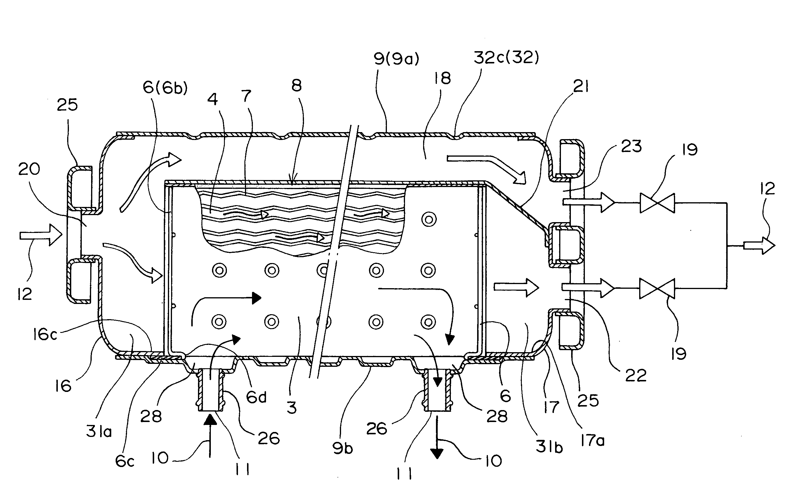
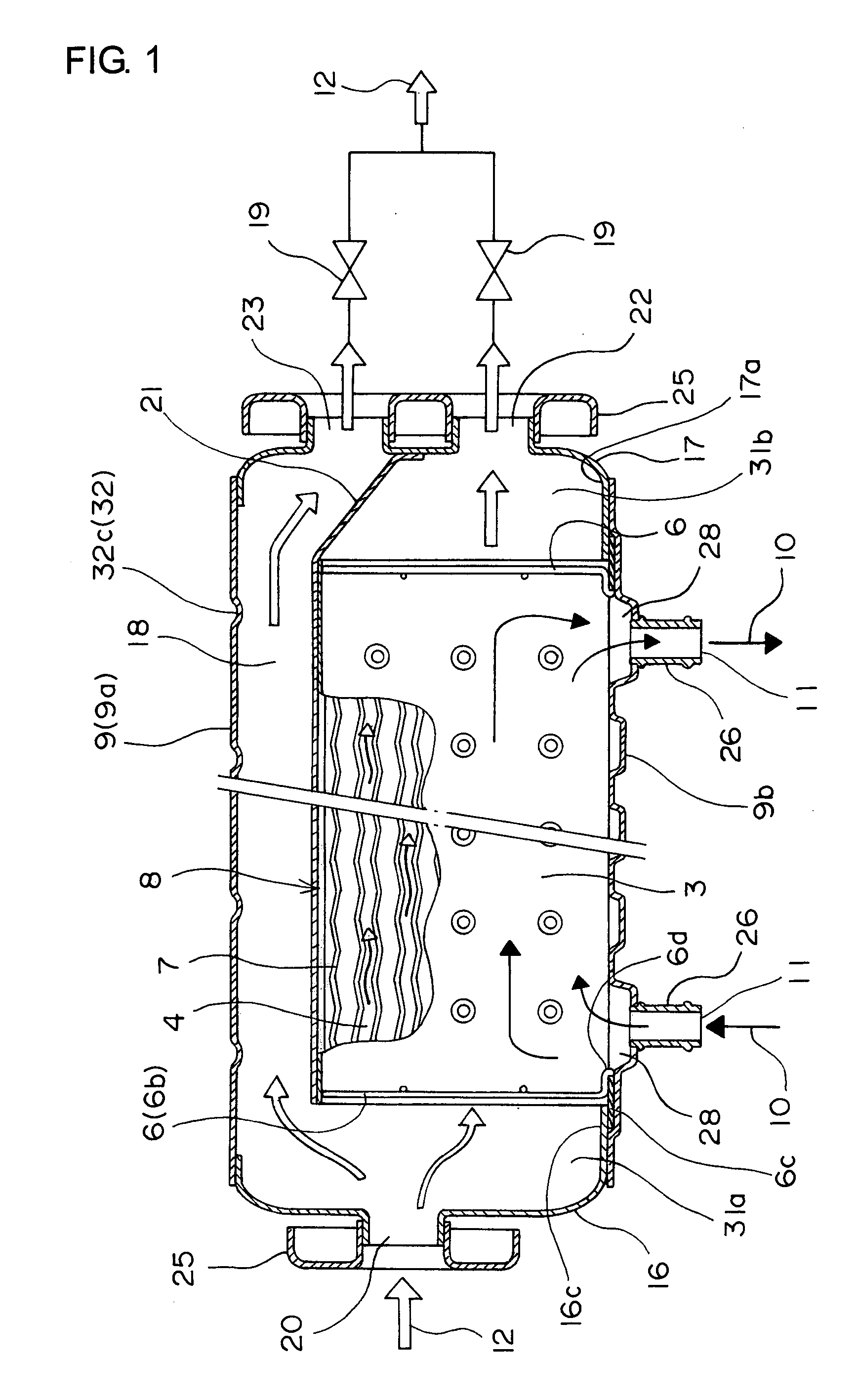
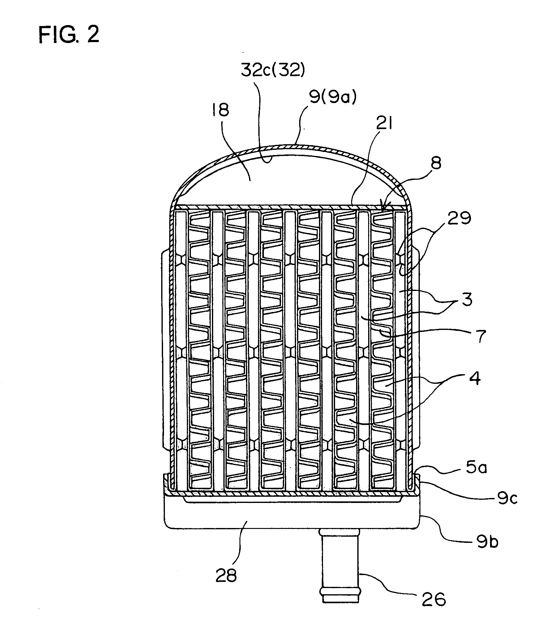
[0054]FIG. 1 is a longitudinal sectional view of an EGR cooler body of the present invention, FIG. 2 is its cross sectional view, FIG. 3 is an exploded perspective view of the EGR cooler at the center part (a partition plate is omitted), FIG. 4 is a partially exploded perspective view of another EGR cooler of the present invention, FIG. 5 is a longitudinal sectional view of still another embodiment, FIG. 6 is an exploded perspective view of its valve portion, FIG. 7 is an assembly explanatory view, FIG. 8 is a partially omitted assembly perspective view of the EGR cooler, and FIG. 9 is an assembly perspective view of the EGR cooler.

[0055] The EGR cooler shown in FIGS. 1 to 3 has a core body 5, a large number of fins 7, a casing 9, a pair of headers 16, 17, and a pair of comb-state members 6.

[0056] The core body 5 is comprised by turning up and bending a strip-shaped metal plate in a...


PUM


Abstract

A bypass duct portion is integrally provided in a casing of an EGR cooler so that heat distortion generated at a part of the casing when bypassing of an exhaust gas is rationally absorbed, and the EGR cooler body and a valve case are brazed/fixed all together so as to improve strength of the valve case, whereby, the bypass duct portion is formed between an inner surface of the casing and the core, a switch is provided for switching and guiding the exhaust gas to either of the core or the bypass duct portion, and a large number of outer ribs formed in the circumferential direction respectively are arranged side by side while being separated from each other in the longitudinal direction in the bypass duct portion of the casing so as to constitute a heat stress absorbing portion. And a cylindrical valve case is integrally formed by deep drawing of a thin metal plate by a press machine, a pair of slits are provided at the rear end of the valve case, both edges of an intra-valve partition plate are inserted into the slits, support projection portions are provided on both faces of the both edge portions of the intra-valve partition plate, and the edge of the slit is supported by the support projection portion. And an opening of the valve case is integrally brazed/fixed to an opening of a header portion of the casing.

Description

BACKGROUND OF THE INVENTION [0001] The present invention relates to an EGR cooler used for cooling an exhaust gas recirculation device of an automobile and particularly to those provided with a bypass duct portion for exhaust gas integrally with a casing of the EGR cooler. [0002] A conventional EGR cooler is made of an assembly of a large number of flat tubes or a large number of plates, a large number of fins, a casing and a header, in which cooling water is made to communicate through the casing side and an exhaust gas is made to communicate inside each of the flat tubes or the like. If the temperature of the exhaust gas is at predetermined temperature or less, the gas is not to pass through the EGR cooler, but another bypass passage or a bypass integral with the EGR cooler is provided to be passed. [0003] This is proposed in Japanese Patent Application Laid-Open No. 2004-278351 and Japanese Patent Application Laid-Open No. 2004-257366, for example. [0004] The conventional EGR coo...

Claims


Application Information

Patent Timeline
Patent Type & Authority Applications(United States)
IPC IPC(8): F02B47/08
CPCF02M25/0714F02M25/0729F02M25/0737F28D9/0025F28F2265/26F28F9/00F28F9/005F28F2220/00Y02T10/121F28D21/0003F02M26/11F02M26/26F02M26/32
Inventor NAKAMURA, YOICHI
Owner T RAD CO LTD
Why Eureka
Try Eureka