Method for Modifying Surface of Counter Electrode and Surface-Modified Counter Electrode

a technology of counter electrodes and surface modifications, which is applied in the direction of electrolytic capacitors, coatings, solid-state devices, etc., can solve the problems of increasing the cost of fabrication, affecting the conversion efficiency of solar energy into electric energy, and affecting the conversion efficiency of solar energy into electricity, etc., to achieve the effect of improving the affinity of the counter electrode, reducing the interface resistance between the counter electrode and the polymer electrolyte, and increasing the electron transfer rate at the interfa

Inactive Publication Date: 2007-12-20
SAMSUNG SDI CO LTD
View PDF4 Cites 18 Cited by
  • Summary
  • Abstract
  • Description
  • Claims
  • Application Information

AI Technical Summary

Benefits of technology

[0013]The present invention overcomes the problems of the prior art, and one aspect of the present invention includes providing a method for modifying the surface of a counter electrode by treating the surface of the counter electrode with a polyethylene glycol derivative having a pendant group (e.g., a thiol group) at one end to improve the affinity of the counter electrode for a polymer electrolyte, so that the interface resistance between the counter electrode and the polymer electrolyte is decreased and the electron transfer rate at the interface is increased, thus achieving improved energy conversion efficiency.
[0014]Another aspect of the present invention includes providing a counter electrode for a photovoltaic device whose surface is modified so as to improve the affinity of the counter electrode for a polymer electrolyte.
[0015]Yet another aspect of the present invention includes providing a photovoltaic device with high energy conversion efficiency in which a counter electrode has a high affinity for an electrolyte.

Problems solved by technology

However, silicon-based solar cells require the use of large, expensive equipment and costly raw materials, incurring considerable fabrication costs.
In addition, silicon-based solar cells suffer from numerous difficulties in improving the conversion efficiency of solar energy into electric energy.
However, since dye-sensitized solar cells are wet cells using a liquid electrolyte, leakage or volatilization of the electrolyte solution may occur during long-term use of the solar cells, causing problems of low reliability and poor long-term stability (e.g., rapid decrease in power conversion efficiency) of the solar cells.
However, solar cells using polymer electrolytes have low energy conversion efficiencies, which makes them undesirable for commercialization.
When the polymer electrolyte of the solar cell includes a polymer having a long molecular chain, it is difficult for the polymer electrolyte to infiltrate into pores formed between the nanometer-sized semiconductor particles.
In addition, if the polymer electrolyte insufficiently surrounds the semiconductor nanoparticles and does not provide a complete connection to the semiconductor nanoparticles without any electrical shorting, the current density of the solar cell is greatly decreased.
Alternatively, when the polymer electrolyte of the solar cell includes a liquid- or wax-phase polymer having a short molecular chain, the mechanical properties of the solar cell can be deteriorated and leakage of the electrolyte inevitably occurs as in wet solar cells.
Particularly, since a solid polymer and a metal constitute the counter electrode / electrolyte interface of the solar cell, incomplete contact between the solid materials is caused.
This incomplete contact makes the transfer of electrons between the counter electrode and the electrolyte layer difficult as compared to when a liquid electrolyte is used, thus leading to a reduction in the power conversion efficiency of the solar cell.

Method used


Image

  • Method for Modifying Surface of Counter Electrode and Surface-Modified Counter Electrode
  • Method for Modifying Surface of Counter Electrode and Surface-Modified Counter Electrode
  • Method for Modifying Surface of Counter Electrode and Surface-Modified Counter Electrode

Examples


examples 1 to 4

Fabrication of Test Devices

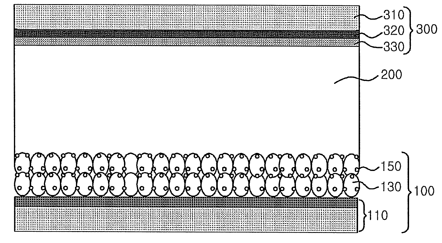
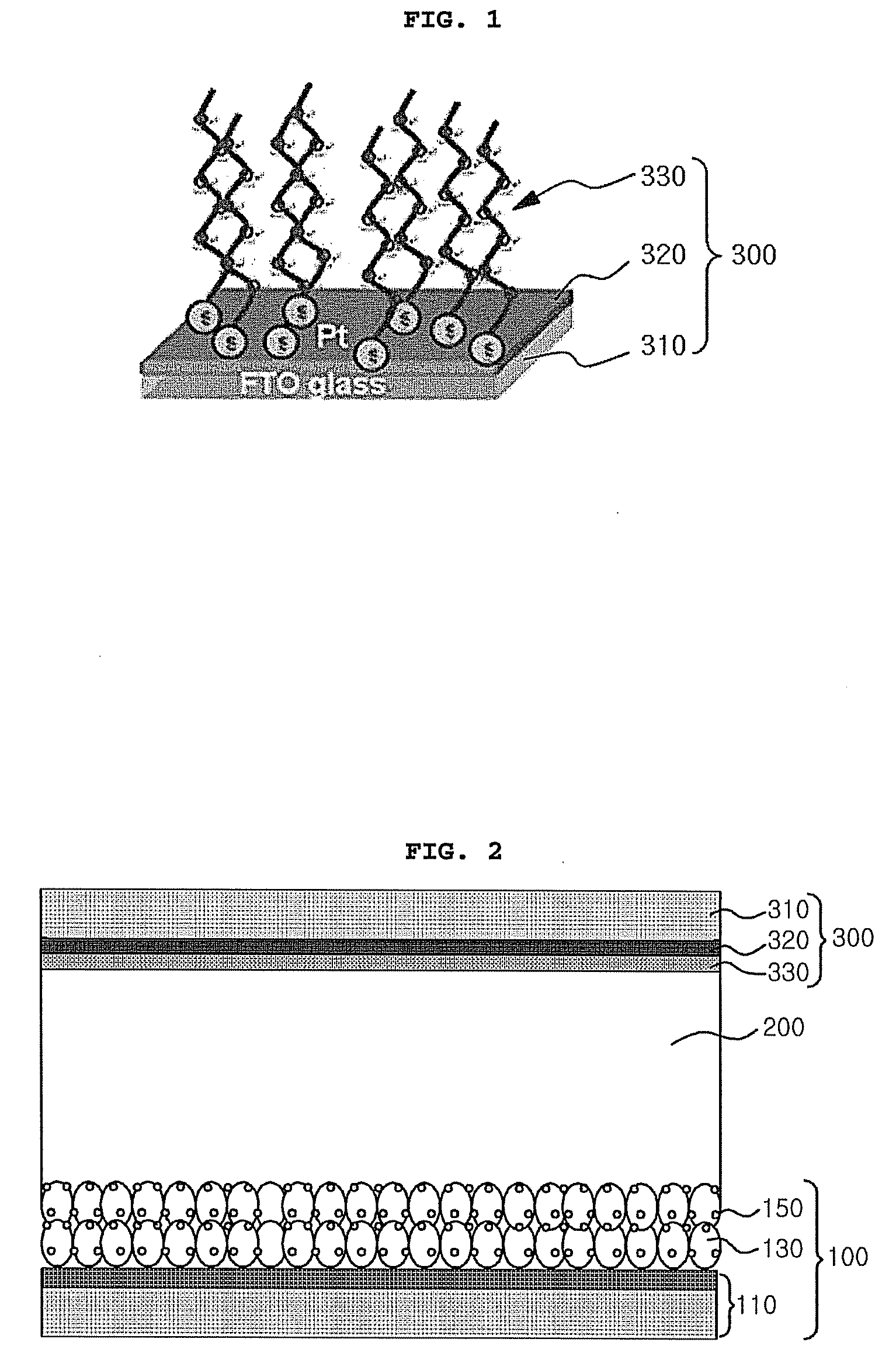
[0068]After fluorine-doped tin oxide (FTO) was sputtered on a glass substrate, a paste of anatase-type TiO2 particles having an average particle diameter of about 13 nm was coated thereon by screen printing and dried at about 70° C. for about 30 minutes. After completion of the drying, the resulting structure was placed in an electric furnace, heated at a rate of about 3 degrees Celsius per minute (° C. / min) in air, maintained at about 450° C. for about 30 minutes, and cooled at a rate of about 3° C. / min to form a porous TiO2 film having a thickness of about 12 micrometers (μm). Subsequently, the glass substrate, on which the metal oxide layer was formed, was dipped in an about 30 millimolar (mM) solution of a cis-bis(isothiocyanato)bis(2,2′-bipyridyl-4,4′-dicarboxylato)-ruthenium(II) bis-tetrabutylammonium dye (N719, Solaronix) in t-butanol and acetonitrile (1:1 (v / v)) for about 24 hours and dried to adsorb the dye on the surface of the TiO2 layer. After ...


PUM


Abstract

Disclosed herein is a method for modifying the surface of a counter electrode. According to the method, the surface modification is achieved by treating the surface of a counter electrode with a polyethylene glycol derivative having a pendant group at one end. Also disclosed is a counter electrode whose surface is modified by the method. The electron transfer rate at the interface between the counter electrode and an electrolyte layer of a photovoltaic device is increased and the affinity of the counter electrode for the electrolyte layer is improved, resulting in an improvement in the power conversion efficiency of the photovoltaic device.

Description

[0001]This application claims priority to Korean Patent Application No. 2006-54801 filed on Jun. 19, 2006, and all the benefits accruing therefrom under 35 U.S.C. § 119, the contents of which are herein incorporated by reference in its entirety.BACKGROUND OF THE INVENTION[0002]1. Field of the Invention[0003]The present invention relates to a method for modifying the surface of a counter electrode, and a counter electrode whose surface is modified by the method. More specifically, the present invention relates to a method for modifying the surface of a counter electrode by treating the surface of the counter electrode with a polyethylene glycol derivative having a pendant group at one end, thereby achieving an increased electron transfer rate at the interface between the counter electrode and an electrolyte layer of a photovoltaic device and improved affinity of the counter electrode for the electrolyte layer; and a counter electrode whose surface is modified by the method.[0004]2. D...

Claims


Application Information

Patent Timeline
Patent Type & Authority Applications(United States)
IPC IPC(8): H01L31/00B05D5/12
CPCH01G9/2022H01G9/2031Y02E10/542H01L51/0086H01G9/2059H10K85/344H01L31/04H01L31/0224H01L31/18
Inventor SOHN, BYUNG HEEPARK, SANG CHEOLKANG, YONG SOOLEE, YOUNG GUN
Owner SAMSUNG SDI CO LTD
Why Eureka
Try Eureka