Mechanical shaft seal

a mechanical shaft and seal technology, applied in the direction of engine seals, machines/engines, leakage prevention, etc., can solve the problems of increased cost, abrasive solids, and areas around rotating shafts that are especially susceptible to the release of heated solids, so as to avoid pneumatic lines or maintenance, easy assembly and installation, and adequate force

Active Publication Date: 2007-12-20
PLATTCO
View PDF35 Cites 6 Cited by
  • Summary
  • Abstract
  • Description
  • Claims
  • Application Information

AI Technical Summary

Benefits of technology

[0006]An advantage of the invention is that such a mechanical shaft seal is typically self-contained and avoids the need for pneumatic lines or maintenance.
[0007]Another advantage of the invention is that such a mechanical shaft seal is easily assembled and installed onto dry-material-handling equipment.
[0008]The combination of such a seal and dry-material-handling equipment is another aspect of the invention.
[0009]A feature of the mechanical shaft seal assembly of the present invention is a grease chamber that prevents solid particles from reaching the main seal by migration within the mechanical shaft seal. By keeping solids away from the main seal, the present mechanical shaft seal is able to maintain adequate force and prevent a breach between seal faces. The grease chamber also lubricates seal faces within the mechanical shaft seal to prevent seal faces from sticking to each other.
[0010]An aspect of the present invention provides a mechanical shaft seal adapted to be mounted externally such that one end thereof comprising a seal assembly is within a pressurized system containing dry material. Such a mechanical shaft seal desirably has a gland used to mount the mechanical shaft seal externally such that one end of the gland is exposed to the external atmosphere and the opposite end is mated with the sealing assembly, the gland having a bore therethrough to enable the gland to house a sealed bearing and a rotor sleeve, the rotating seal assembly also housing the rotor sleeve for rotation therein, and the rotor sleeve having a bore therethrough to enable the rotor sleeve to surround and sealingly engage a shaft for rotation therewith.
[0011]A more specific aspect of the invention provides a seal assembly comprising a grease housing, a lip seal, a grease chamber (a chamber having a substantial amount of grease contained therein), and a single-spring seal that prevents the migration of solid material into the rotating parts of mechanical shaft seal (which migration may result in damage due to the abrasive quality of the dry material), the grease housing and the lip seal having a bore to receive a rotor sleeve therethrough, and a stationary seat mounted around the rotor sleeve, the single-spring seal being mounted around the rotor sleeve and constrained in sealing engagement with the stationary seat, and the grease chamber bounded by the lip seal, grease housing, and rotor sleeve.

Problems solved by technology

The area around a rotating shaft is especially susceptible to the release of heated, abrasive solids.
As those skilled in this art will appreciate, shaft seals for dry-material-handling equipment that operate under positive pressure can sometimes fail.
Disadvantages of such pneumatic seals are increased cost (due to the need for maintenance and operation of air lines) and the risk of interrupted air supply.
When air supply is interrupted, abrasive particles can escape from the system or into the housing of a seal.
When such abrasive solids are introduced into shaft seal housing, they can quickly wear away rotating parts, leading to failure.
The abrasive material will erode the vessel and surrounding parts.

Method used


Image

  • Mechanical shaft seal
  • Mechanical shaft seal
  • Mechanical shaft seal

Examples


Embodiment Construction

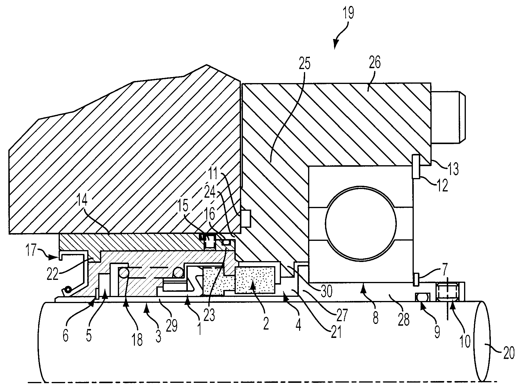
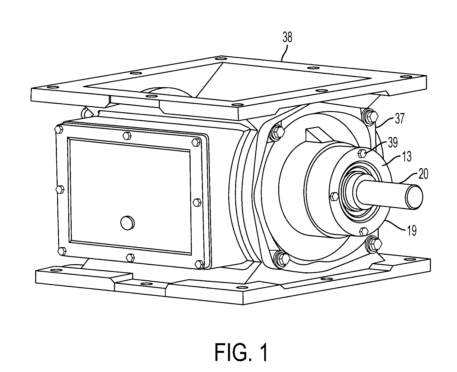
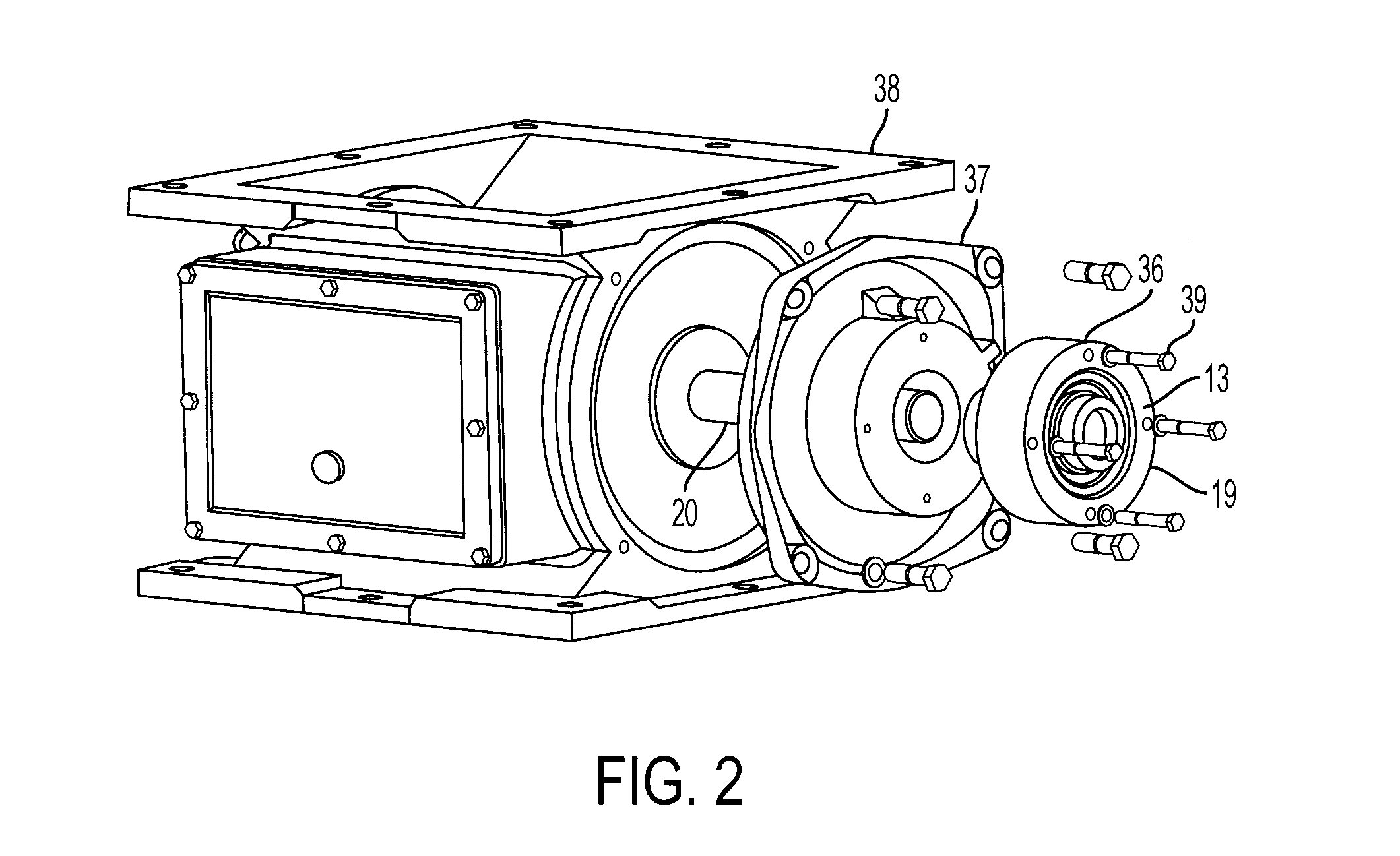
[0022]Referring to FIG. 1 and FIG. 2, a mechanical shaft seal embodying the present invention is adapted to be externally and sealingly mounted onto dry-material-handling equipment, such as onto a flap valve (e.g. an Airlock® valve sold by Plattco Corporation (Plattsburgh, N.Y.)), or a flap valve, or a diverter valve or other valve maintaining a pressure differential between two environments. Applications for a mechanical shaft seal of the invention include, but are not limited to, installation around an entry point of a mixer or packer.

[0023]Gland 13 for the mechanical shaft seal 19 is exposed to the outside atmosphere and secured to end cap 37, e.g. by fastening bolts 39 through apertures 36. End cap 37 is then attached to the side wall of flap valve 38. Shaft 20 extends from within flap valve 38 and through end cap 37 and mechanical shaft seal 19. A bore through the center axis of the mechanical shaft seal 19 is large enough to accept a rotating shaft 20 and prevents the release ...


PUM


Abstract

An improved mechanical shaft seal to give a tight seal between relatively rotating machine parts and prevent the escape of particulate material into the atmosphere or into the mechanical components of the housing under adverse operating conditions. The seal provides a grease chamber that prevents solid particles from reaching the main seal by migration within the mechanical shaft seal.

Description

CROSS-REFERENCE TO RELATED APPLICATIONS[0001]This application claims priority from U.S. Provisional Application 60 / 804,873, filed Jun. 15, 2006, the entire contents of which are incorporated herein by reference.BACKGROUND[0002]This invention relates to self-contained seals, particularly to devices and methods for providing a seal between two relatively rotatable machine parts, particularly suited for use in equipment for handling dry powdered material.[0003]Manufacturing processes, such as mining and minerals, cement, or bulk powder production, require equipment that is capable of conveying, blending, mixing, or metering solids. In order to facilitate the movement of dry material through processing equipment a rotating shaft is often used, such as an agitator in the case of blending. Industries, like cement or mineral production, also force the movement of dry material that is in the form of small particles or powder by using pressurized vessels or lines. The vessels and lines used ...

Claims


Application Information

Patent Timeline
Patent Type & Authority Applications(United States)
IPC IPC(8): F16J15/34
CPCF16J15/3404
Inventor SURPRENANT, DEANNOEL, PATRICK J.SPOONER, JEFFREY S.
Owner PLATTCO
Why Eureka
Try Eureka