Rotor for Electric Motor, Compressor Unit Provided with Rotor, Method for Producing a Rotor for an Electric Motor

a technology for electric motors and compressor units, which is applied in the direction of synchronous motors, magnetic circuit rotating parts, magnetic circuit shapes/forms/construction, etc., can solve the problem of not providing a connection between rods and cylinders, and achieves high rotational speeds, improves the rotary performance of the rotor, and increases the strength of the rotor

Active Publication Date: 2007-12-20
SIEMENS AG
View PDF7 Cites 26 Cited by
  • Summary
  • Abstract
  • Description
  • Claims
  • Application Information

AI Technical Summary

Benefits of technology

[0012] Furthermore, it is expedient for the rotor to be provided with two end rings which extend around the cylindrical core and retain the conductive rods and the short-circuit rings in the axial direction. Rings of this nature increase the strength of the rotor and shield the axial ends of the short-circuit rings.
[0013] In particular, the end rings are provided with balancing openings on their outer side. Balancing openings of this type are provided in order to remove material at that location or to create the option of adding a material in order to bring the rotor into balance. This improves the rotary performance of the rotor at high rotational speeds and causes the loading on a bearing arrangement for the rotor to decrease.
[0014] In one embodiment, the conductive rods comprise two parallel walls. It is advantageous for the longitudinal grooves in the cylinder core also to comprise substantially parallel walls, with the result that both the longitudinal grooves and the conductive rods are simple to produce and it is easy for the conductive rods to be fitted in the longitudinal grooves.

Problems solved by technology

One drawback of the known rotor is that in reality it does not provide a connection between the rods and cylinder which is able to withstand the centripetal forces which occur at high rotational speeds.

Method used


Image

  • Rotor for Electric Motor, Compressor Unit Provided with Rotor, Method for Producing a Rotor for an Electric Motor
  • Rotor for Electric Motor, Compressor Unit Provided with Rotor, Method for Producing a Rotor for an Electric Motor
  • Rotor for Electric Motor, Compressor Unit Provided with Rotor, Method for Producing a Rotor for an Electric Motor

Examples


Embodiment Construction

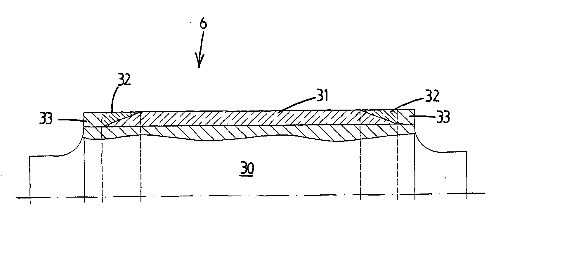
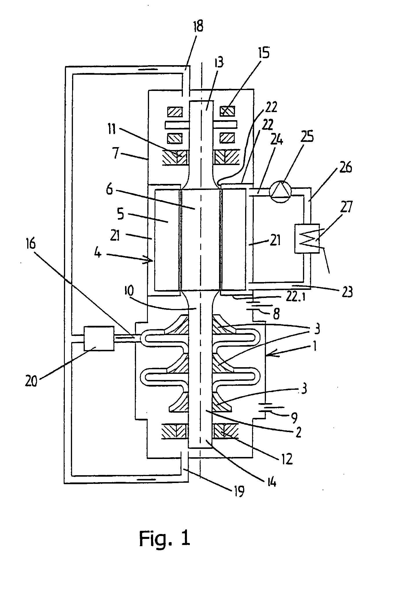
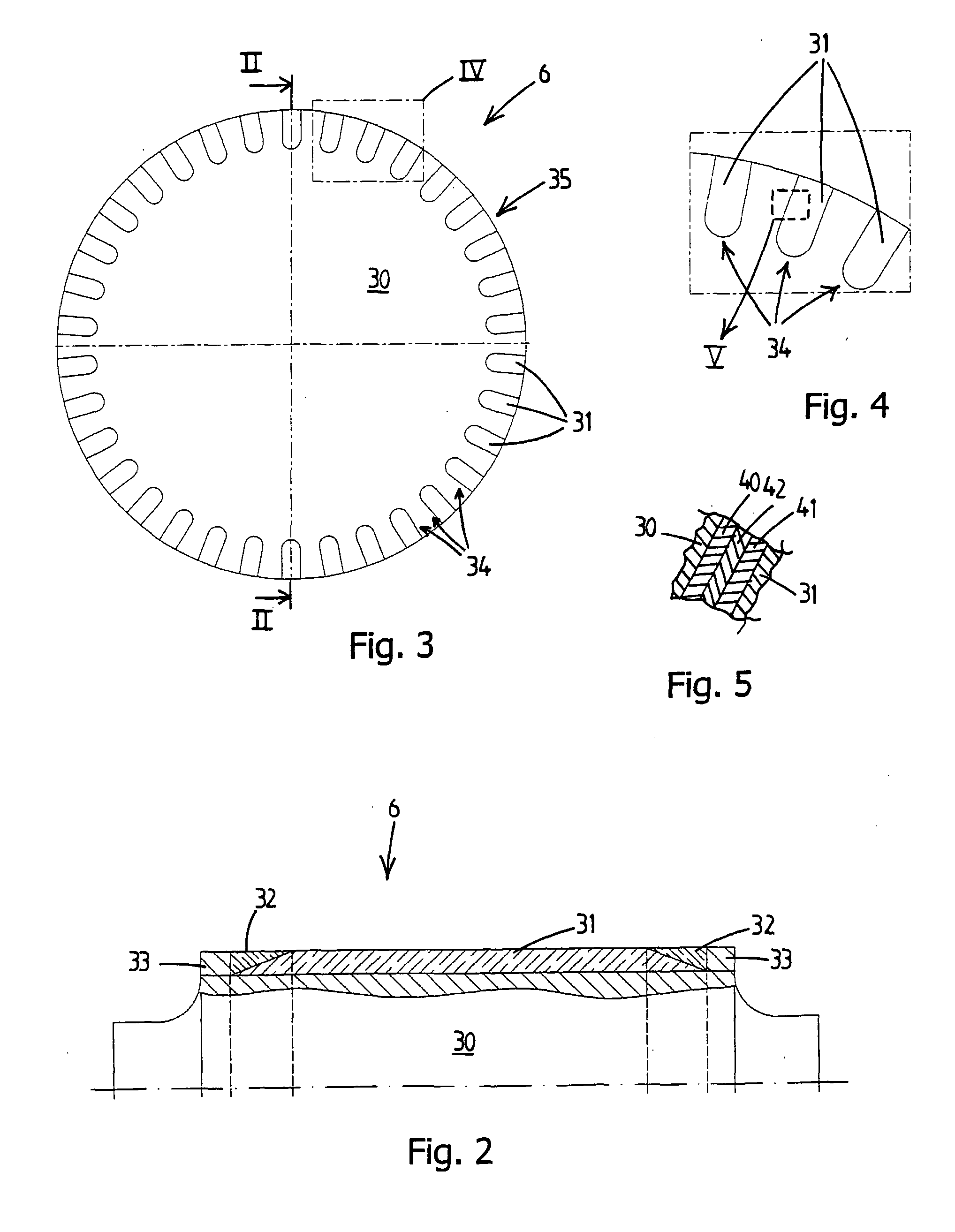
[0039] The compressor unit illustrated in FIG. 1 comprises a centrifugal compressor 1 for compressing a gas, for example process gas, having a rotor 2 with one or more, in this case three compressor impellers 3 and an electric motor 4 having a stator 5 and a rotor 6 for driving the rotor 2 of the compressor. The compressor 1 and the electric motor 4 are accommodated in a common gastight housing 7 which is provided with a gas inlet 8 and a gas outlet 9.

[0040] The rotor 2 of the compressor 1 and the rotor 6 of the electric motor 4 form part of a common rotor shaft 10 which forms a single unit. The rotor shaft 10 is mounted in two magnetic radial bearings 11 and 12 which are each arranged in the vicinity of one end 13 and 14, respectively, of the rotor shaft 10, and a magnetic axial bearing 15 arranged in the vicinity of the radial bearing 11.

[0041] The compressor unit is provided with a cooling system for cooling the magnetic bearings 11, 12, 15 and the rotor 6 of the electric motor...


PUM

PropertyMeasurementUnit
rotational speedsaaaaaaaaaa
electrically conductiveaaaaaaaaaa
conductiveaaaaaaaaaa

Abstract

A rotor for an electric motor according to the invention comprises a substantially cylindrical core, conductive rods and two short-circuit rings. The cylindrical core is formed from a core material and provided with a plurality of longitudinal grooves which extend substantially in the direction of the cylinder axis. The conductive rods are formed from an electrically conductive material and are provided in the longitudinal grooves of the cylindrical core. The two short-circuit rings conductively connect the axial ends of the conductive rods to one another. A diffusion layer extends between the conductive rods and the cylindrical core. The diffusion layer comprises a diffusion material.

Description

CROSS REFERENCE TO RELATED APPLICATIONS [0001] This application is the US National Stage of International Application No. PCT / NL2005 / 000428, filed Jun. 10, 2005 and claims the benefit thereof. The International Application claims the benefits of Dutch Patent application No. 1026424 filed Jun. 15, 2004. All of the applications are incorporated by reference herein in their entirety.FIELD OF INVENTION [0002] The invention relates to a rotor for an electric motor, to a compressor unit provided with a rotor of this type, and to a method for producing a rotor for an electric motor. BACKGROUND OF THE INVENTION [0003] A rotor of this type is known from JP H 3-261354. This document discloses a steel cylinder, the surface of which is provided with a plurality of longitudinal grooves. The longitudinal grooves are relatively narrow at the surface of the cylinder and widen out beneath the surface to form substantially round cross sections. Copper rods are provided in the longitudinal grooves and...

Claims


Application Information

Patent Timeline
Patent Type & Authority Applications(United States)
IPC IPC(8): H02K1/22H02K15/02H02K17/16B23K35/00H02K15/00
CPCH02K15/0012Y10T29/49012H02K17/165
Inventor BODE, RALFGRAF, WOLFRAM
Owner SIEMENS AG
Why Eureka
Try Eureka