Electromagnetic Enhancement and Decoupling

a technology of electromagnetic enhancement and decoupling, applied in the direction of mechanical actuation of burglar alarms, instruments, and using reradiation, etc., can solve the problems of reducing the read range to unacceptable levels, difficult to track metal objects such as cages or containers with uhf rf, and other more expensive location systems

Active Publication Date: 2007-12-20
HID GLOBAL CORP
View PDF80 Cites 43 Cited by
  • Summary
  • Abstract
  • Description
  • Claims
  • Application Information

AI Technical Summary

Benefits of technology

[0010] It is therefore an object of the invention to provide a mount for an EM tag which acts as an electromagnetic radiation decoupler material which mitigates at least some of the problems associated with prior art systems, namely those of thickness, size and flexibility.
[0011] It is a further object of the invention to provide apparatus for coupling incident energy into an electronic device or tag, while at the same time isolating such coupling effect from the potentially adverse effects of a substrate on which the device or tag is mounted.

Problems solved by technology

One commonly experienced disadvantage with such tags, especially passive tags, is that if directly placed on (or within a several millimetres of) a metal surface their read range is decreased to unacceptable levels and—more typically—the tag cannot be read or interrogated.
Therefore, the tracking of metal articles such as cages or containers is very difficult to achieve with UHF RF tags and so other more expensive location systems have to be employed, such as GPS.
UHF RFID tags also experience similar problems when applied to certain other surfaces which interact with RF (radio frequency) electromagnetic waves, such as, certain types of glass and surfaces which possess significant water content, examples including certain types of wood with a high water or sap content.
Problems will also be encountered when tagging materials which contain / house water such as, for example, water bottles, drinks cans or human bodies etc.
Clearly, a spacer of this thickness is impractical for many applications and is prone to being accidentally knocked and damaged.
This avoids the need for a large spacer but does require relatively complicated antenna designs which must be different for each tag, therefore adding to the cost and complexity of manufacture.
The design does minimise surface reflection effects but the patch antenna is preferably spaced away from the ground plane by a distance equal to a quarter wavelength which is a large spacing and suffers from the same problems as for the foam spacer mentioned above It also requires a large ground plane which may be not achievable in all circumstances.

Method used


Image

  • Electromagnetic Enhancement and Decoupling
  • Electromagnetic Enhancement and Decoupling
  • Electromagnetic Enhancement and Decoupling

Examples


Embodiment Construction

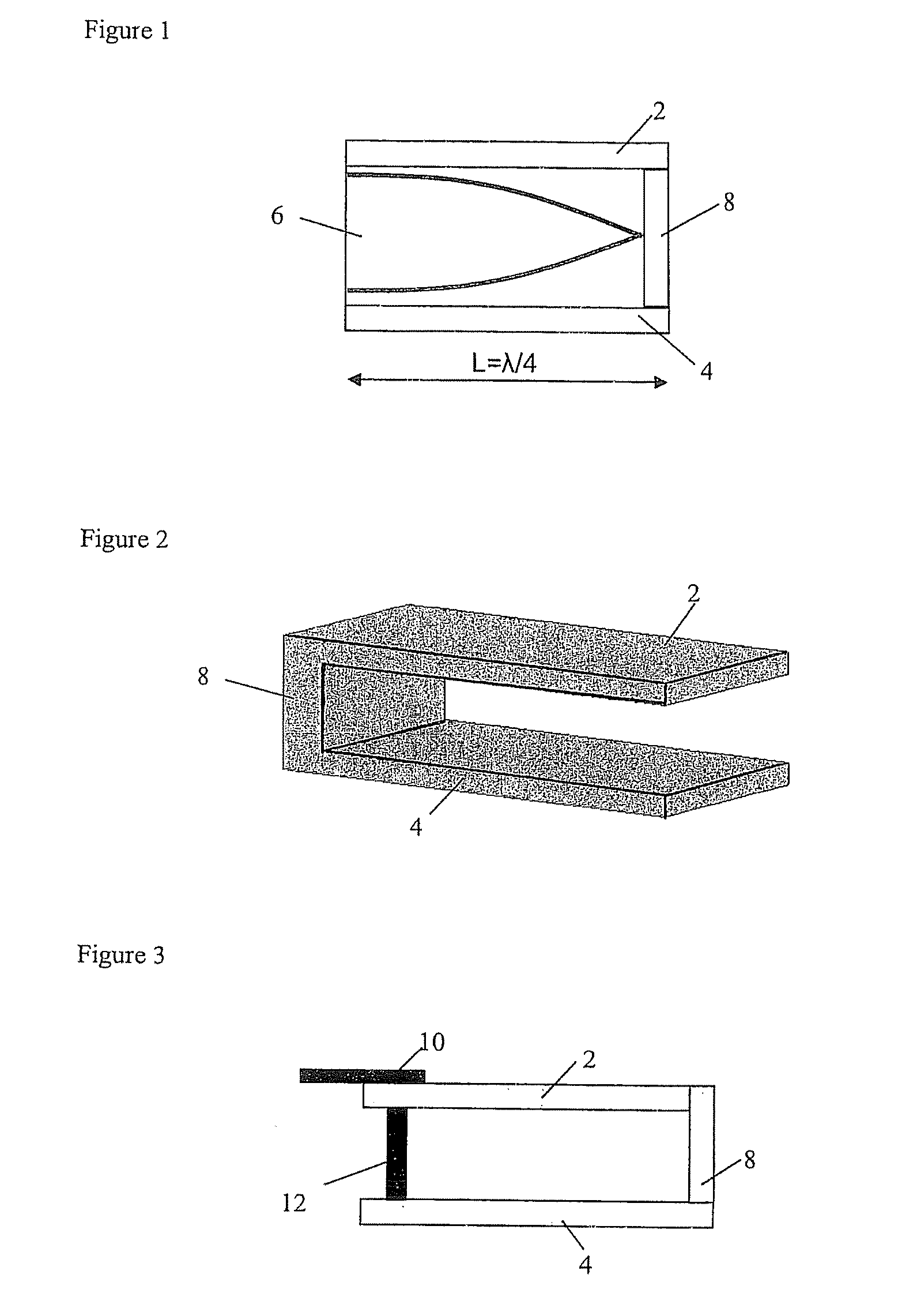
[0089]FIG. 1 shows a side view of a device or decoupler according to the present invention. The decoupler has a layer of metal forming a first conducting side wall 2 spaced apart from and parallel to a another layer of metal forming a second conducting side wall 4. These two side walls enclose a dielectric material 6 which may be air or may be one or more layers of material such as PET. The two conducting side walls define a sub wavelength cavity, one end of which is closed by a conducting end or base portion 8. One or both of the first and second conducting side walls 2, 4 may be continuous with the conducting base portion 8. The end of the cavity opposite the conducting base portion 8 is an open end, i.e. it has no conducting wall. The conducting base portion 8 is the only conducting link between the first and second side walls 2, 4. The decoupler is shown in FIG. 2 in perspective view. For clarity no solid dielectric layer is shown.

[0090] The device is designed to decouple radia...


PUM


Abstract

Apparatus and methods for providing a substantially surface independent tagging system are disclosed. A resonant dielectric cavity is defined between upper and lower conducting layers, and closed at one end by a conducting base portion. Incident radiation couples into the cavity and is resonantly enhanced. An electronic device or tag paced at the edge of the cavity experiences a high electric field strength on account of this enhancement and is driven into operation.

Description

BACKGROUND OF THE INVENTION [0001] (1) Field of the Invention [0002] This invention relates devices which manipulate electromagnetic radiation (EM) and more specifically relates to the field of coupling energy into identification devices such as RF (radio frequency) tags. The invention allows the tag to be decoupled (i.e. isolated) from surfaces which degrade tag performance, such as metallic surfaces. The invention relates to any EM tag, particularly those that rely upon propagating wave interactions (as opposed to the inductive coupling exhibited by magnetic tags). Hence our preferred embodiment involves application to long-range system tags (e.g. UHF-range and microwave-range tags). [0003] (2) Description of the Related Art [0004] Electronic devices which can transmit a modulated electromagnetic signal that can be detected by an appropriate reader are widely used for the identification and tracking of items, particularly for articles in a shop or warehouse environment. Such devic...

Claims


Application Information

Patent Timeline
Patent Type & Authority Applications(United States)
IPC IPC(8): H01Q7/04G08B13/14H01Q1/52
CPCG01V15/00G06K19/07749G06K19/07771H05K9/00H01Q1/2225H01Q1/52H01P7/065G01S13/74H01P7/06G06K19/077H01Q1/22H01Q1/38H01Q9/04H01Q13/08
Inventor BROWN, JAMES ROBERTLAWRENCE, CHRISTOPHER ROBERT
Owner HID GLOBAL CORP
Why Eureka
Try Eureka