Delivery of Data Packets via Aggregated Spatial Distribution Overlay on a Mesh Network

a data packet and spatial distribution technology, applied in the field of mesh networks, can solve the problems of network draining available energy, nodes using bad paths, and affecting the efficiency of data packet delivery, and achieve the effect of saving available energy

Active Publication Date: 2007-12-20
ACEINNA TRANSDUCER SYST CO LTD
View PDF58 Cites 54 Cited by
  • Summary
  • Abstract
  • Description
  • Claims
  • Application Information

AI Technical Summary

Benefits of technology

[0015] In accordance with one embodiment of the present invention, a wireless network and method of operation form a transmission route for data packets or messages from child node or module to parent node or module progressively along a single path toward a central or base station. In addition, if a data packet or message may be dropped during operation due to poor link quality, an embodiment of the present invention facilities “jumping” to alternative paths within the network toward the base station. Also, data that may have been stored because of poor quality or disconnected link for later forwarding, may be aggregated with other data packets for forwarding along a new path established by such a “jump”. In this manner, time-sensitive data transmitted over long-hop networks can be more reliably delivered to the base station along an established route, or along a “jump” to an alternative route. Similarly, in high-density networks, the formation of an alternative “jump” route in accordance with the present invention obviates formation of congested parallel paths with concomitant savings of available energy and avoidance of repetitious attempts to retransmit data packets over a poor-quality link.

Problems solved by technology

If the period between recalculations of the optimal path is too long, nodes may use bad paths.
If the period used is short, the network will drain available energy (usually battery power) rapidly.
Since the variation of link quality over time is difficult to determine, most algorithms choose a single network-wide period based on network lifetime.
In most cases, if a path goes bad between update periods, the data sent along that path is lost.
However, a difficulty associated with end-to-end recovery along a single path is the unreliable characteristics of the wireless communication link.
The error accumulates exponentially over multiple hops from link to link, causing a high probability of packet loss, as illustrated in the graph of FIG. 1.
However, as the number of hops increases along the path, even a set of good quality links has a low probability of delivering data reliably, as illustrated in the graph in FIG. 2.
However, even after 8 retransmissions, such link-level retransmission scheme cannot make a poor-quality link into a high-quality link, and there is still possibility for data to be lost over the path.
However, in networks where data is time-sensitive and must be delivered by a hard deadline, storage for a later date is inappropriate.
For time-sensitive data to be delivered over a single-path mesh network, DTN is an inappropriate solution and an alternative is to then fall back to using retransmissions in order to force the data to the base station hop by hop, expending large amounts of energy.
However, even packet retransmissions have limitations.
Long-hop networks and / or networks where link quality can become excessively poor can still lose data along poor quality paths while expending large amounts of energy.
In addition, retransmissions have a detrimental consequence in high density networks.
Due to the low-bandwidth radios used at each node, retransmissions can saturate the bandwidth, causing congestion.
Congestion decreases the link quality on all surrounding paths with the consequence that all paths within radio distance of the retransmitting node will also begin dropping packets, and this can lead to a full network collapse.

Method used


Image

  • Delivery of Data Packets via Aggregated Spatial Distribution Overlay on a Mesh Network
  • Delivery of Data Packets via Aggregated Spatial Distribution Overlay on a Mesh Network
  • Delivery of Data Packets via Aggregated Spatial Distribution Overlay on a Mesh Network

Examples


Embodiment Construction

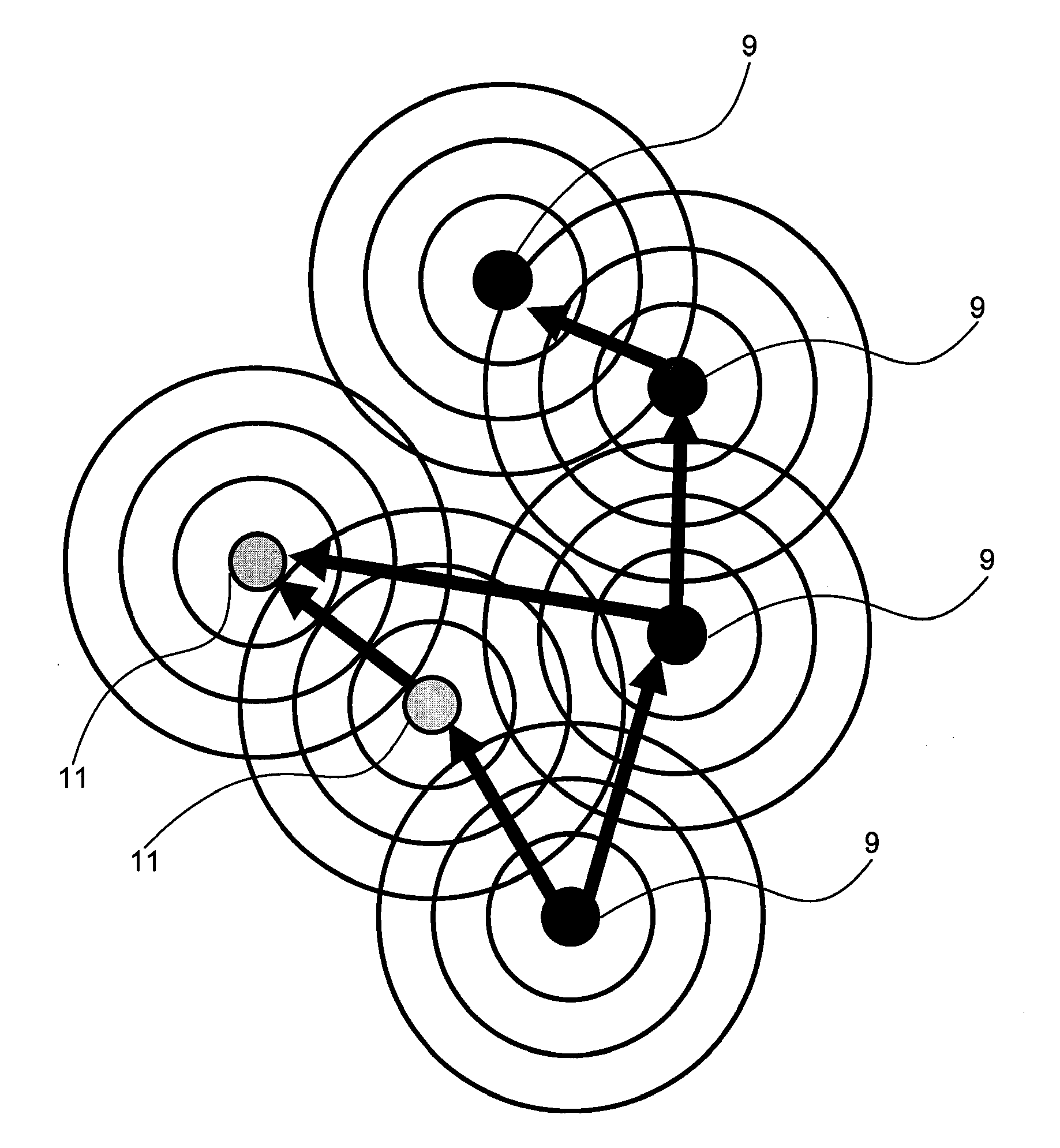
[0036] Referring now to FIG. 3 there is shown a graphic illustration of a segment of a wireless network in which a plurality of nodes or modules 9 are spatially oriented substantially the radio transmission distance away from each toward a base station (not shown). Each such node or module 9 of the Wireless Sensor Network (WSN) uses low-bandwidth radios to create a self-healing wireless mesh network in which each node or module is capable of receiving and transmitting data packets or messages, and of sending a signal indicative of having received a data packet or message from another node. In WSN networks, nodes route data toward a centralized point in the network referred to as a base station. Nodes are battery operated and attempt to increase their lifetime by minimizing radio communication, a highly energy-expensive action. Thus, as illustrated in FIG. 3, routing through the network must attempt to find the most reliable path to deliver data via one or more nodes to a base statio...


PUM


Abstract

A plurality of interactive modules are disposed at spaced locations to form an adaptive wireless network. Each module is capable of receiving transmissions of messages or data packets from other modules, and of transmitting messages or data packets to other modules for forming selected transmission paths via one or more modules toward a base station. Upon failure of a transmission path, a module not capable of transmitting a message along a transmission path toward the base station, transmits a message to other of the plurality of modules to form a new transmission path via such other module.

Description

RELATED APPLICATION [0001] This application is a continuation-in-part of, and claims priority from, application Ser. No. 11 / 433,194 entitled “Adaptive Network and Method” filed on May 11, 2006 by A. Broad et al, which is a continuation-in-part of application Ser. No. 11 / 345,737 entitled “Interactive Surveillance Network and Method,” filed on Feb. 1, 2006 by A. Broad et al, which is a continuation-in-part of application Ser. No. 11 / 152,350 entitled “Adaptive Surveillance Network and Method,” filed on Jun. 13, 2005 by A. Broad, which is a continuation-in-part of application Ser. No. 11 / 095,640 entitled “Surveillance System and Method,” filed on Mar. 30, 2005 by A. Broad et al, which applications are incorporated herein in the entirety by this reference to form a part hereof.FIELD OF THE INVENTION [0002] This invention relates to mesh networks and more particularly to system and method for improving probability of packet delivery over low-bandwidth, poor quality links of a wireless net...

Claims


Application Information

Patent Timeline
Patent Type & Authority Applications(United States)
IPC IPC(8): H04Q7/00H04W40/22H04W40/26
CPCH04W40/26H04W40/22
Inventor KAPUR, RAHULTURON, MARTIN
Owner ACEINNA TRANSDUCER SYST CO LTD
Why Eureka
Try Eureka