
Multi-part implants for combined repair of hyaline and meniscal cartilage in joints

Inactive Publication Date: 2007-12-20
MANSMANN KEVIN A
View PDF19 Cites 50 Cited by
  • Summary
  • Abstract
  • Description
  • Claims
  • Application Information

AI Technical Summary

Benefits of technology

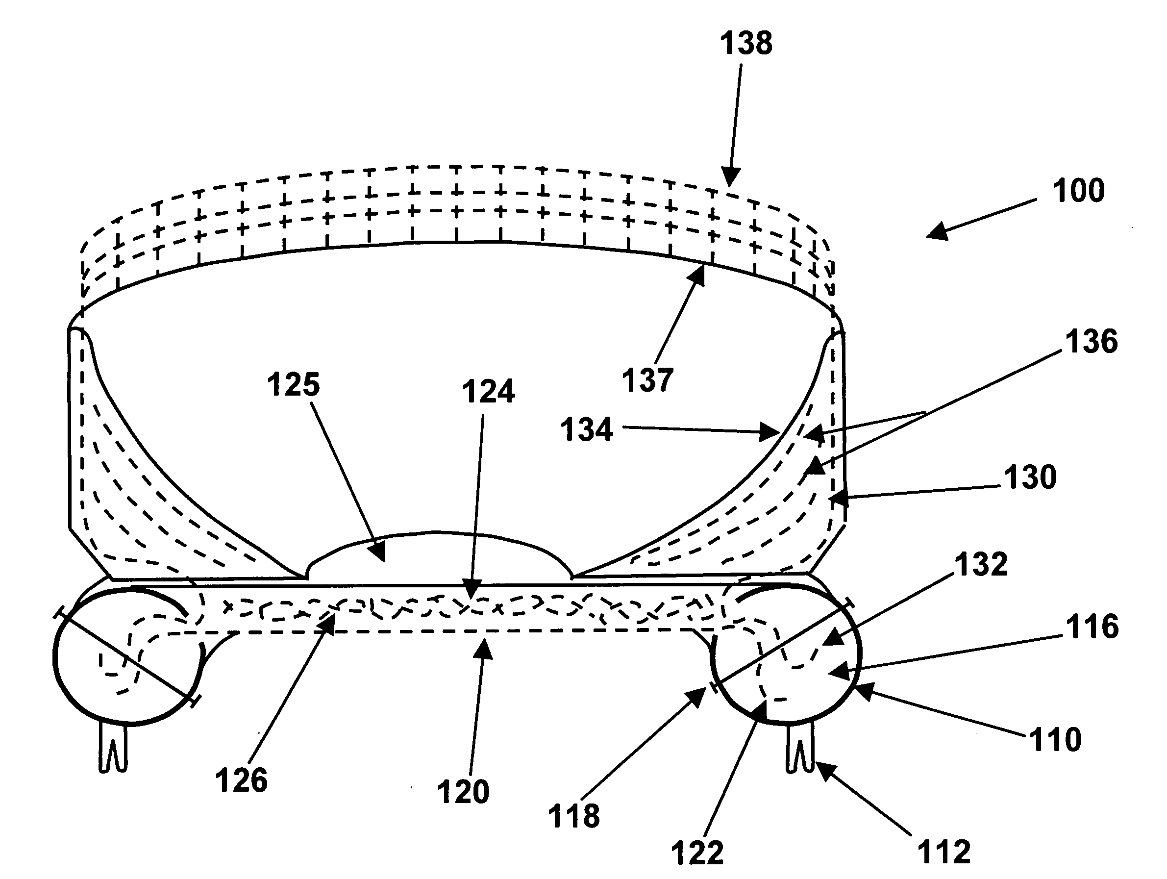
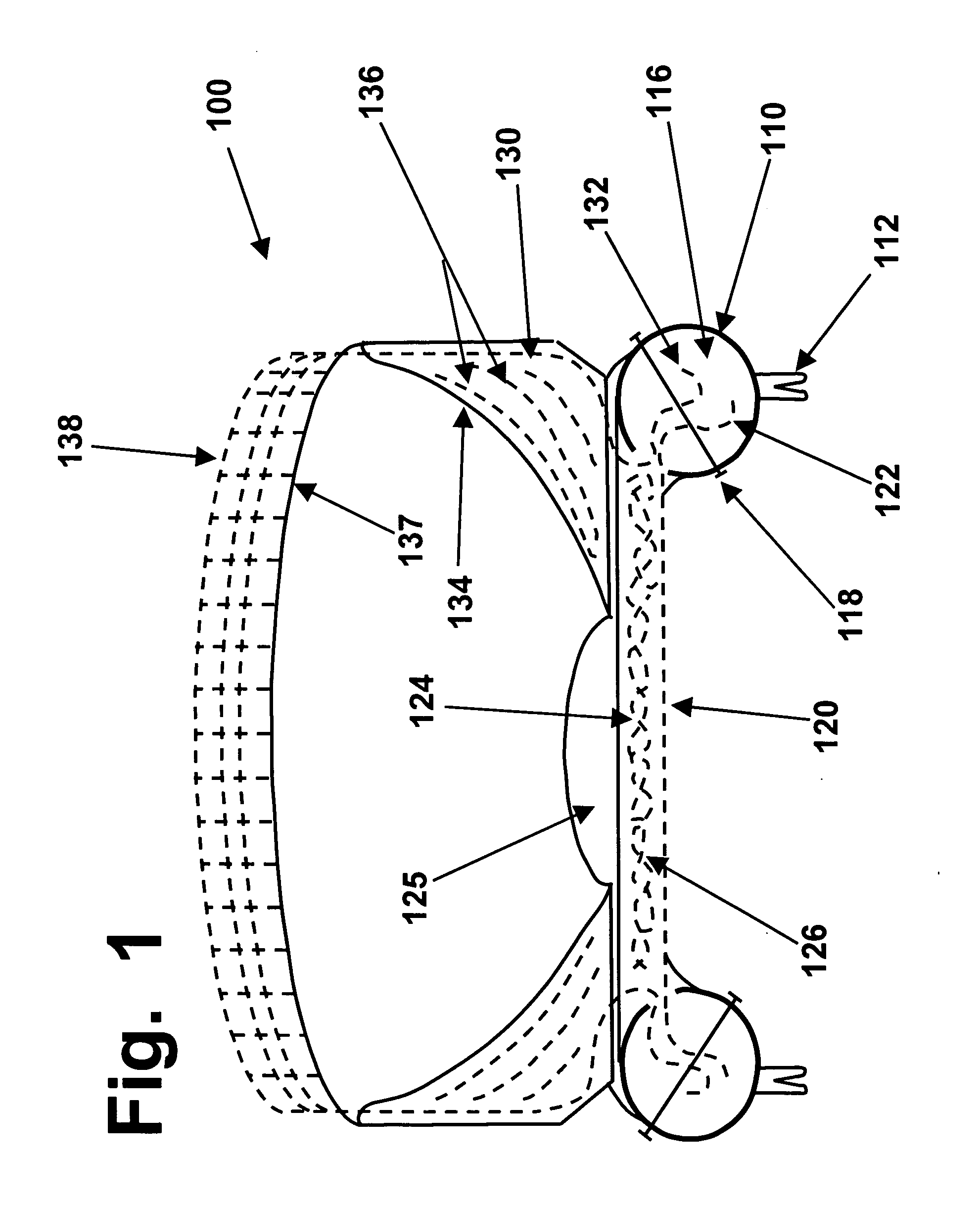
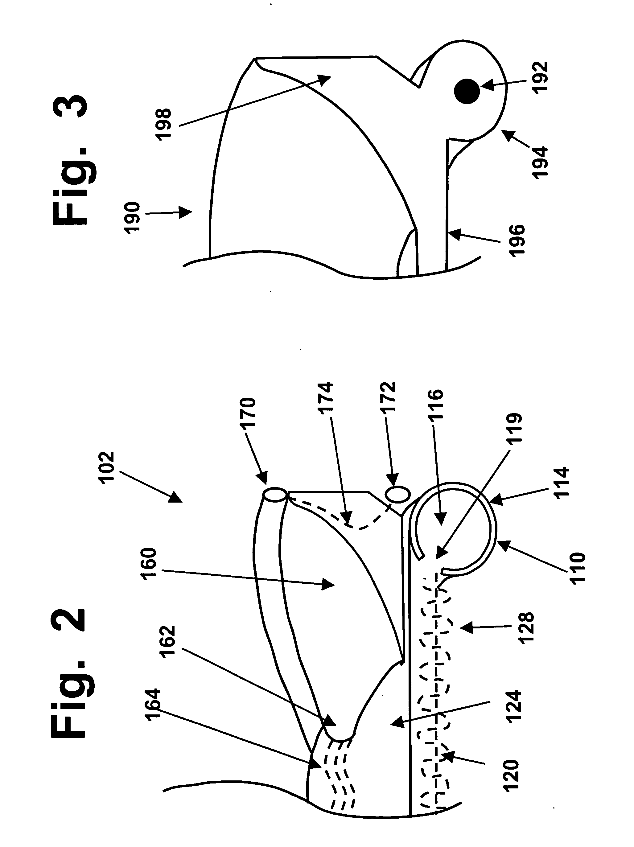
[0033]Devices, methods, and tools are disclosed for surgical implants that use a combination of anchoring components to replace meniscal cartilage segments in knees, in ways that provide strong reinforcement while also emulating the anchoring of natural meniscal segments. Such anchoring components include: (1) an anchoring rim made of a nitinol alloy or other shape-memory material that can be manipulated by squeezing, chilling, or other means, to minimize tissue damage during insertion; (2) anchoring receptacles that are anchored in hard bone before an implant is inserted into a knee joint, while room to work is available; (3) anchoring pegs on the anchoring rim, which will lock in place when pushed into the anchoring receptacles; (4) a polymer insert gripped by the anchoring rim, which will anchor a flexible reinforcing fabric that is also embedded in an arc-shaped polymer segment that will replace a meniscal wedge; (5) a flexible fabric extending above the upper edge of the meniscal polymer segment, which can be sutured or stapled to the knee capsule or a remnant of a meniscal rim; and, (6) fibrous material that extends out of the tips of the meniscal polymer segment, which can be anchored to ligament or meniscal remnants affixed to the tibial spine. All of these components can be provided in a single implant that can be arthroscopically inserted. The implant can also provide a polymer layer that will replace hyaline cartilage on a tibial plateau, with a porous bottom surface that will promote tissue ingrowth for even stronger anchoring.
[0034]Arthroscopic tools are also disclosed for preparing a tibial bone to receive and support such an implant. One set of tools will create a smooth planed surface from which natural cartilage has been removed, while another set of tools will create a groove around the periphery of the surface, to help hold and reinforce the anchoring rim of an implant.

Problems solved by technology

The upper surface of a meniscus is also smooth, wet, and slippery.
By contrast, hyaline cartilage has much shorter structural and reinforcing fibers, and as a result, it is not as strong or tough as fibrocartilage.
Because meniscal segments in human knees are subjected to frequent combinations of compressive and tensile stresses (and sometimes abrasion, especially in people suffering from chondromalacia, arthritis, injuries, or other problems that can cause a loss of smoothness in cartilage surfaces), meniscal damage often occurs in humans, and occasionally in livestock and other animals.
However, because of their complex structures and anchoring, and because of the need to create and sustain very smooth and constantly wet surfaces on both the upper and lower surfaces of each meniscal wedge, meniscal implants in the prior art have not been entirely adequate.
That device has some utility; however, because its anchoring structure does not resemble or emulate the anchoring system of a healthy native meniscal segment, that type of implant could not move, respond, and behave in the same ways that a natural meniscal segment will move and behave.
That may have offered some improvement over prior designs, but it still fell short of being optimal.
In particular, the '667 patent did not address the crucial issue of how the anchoring pins that were described, for anchoring that type of implant, apparently would need to penetrate and damage the natural cartilage (or a cartilage-replacing implant) that sits on top of the tibial plateau.
That is a major issue, because the act of driving steel pins through the smooth-surfaced cartilage on a tibial plateau would pose grave risks of damaging that cartilage surface, and creating an abrasive surface that would also damage the femoral runner as well.
However, that apparent problem was not addressed in the Richmond '667 patent.
However, those and numerous other efforts to replace cartilage in load-bearing joints, by using transplanted cells to generate new biological cartilage, have generally failed to overcome the problems that arise when a resorbable implant begins to release particles and debris into a repaired joint.
Because of that problem, the use of resorbable implants that hold transplanted cells, for regenerating new cartilage, has been limited to only two relatively small niches: (i) cosmetic repair of cartilage in body parts that are not subjected to loadings and stresses, such as ears and noses; and, (ii) repair of small joint defects caused by injuries, usually limited to relatively young patients.
Since the crucial problem of debris being released by partially-dissolved resorbable implants has not been overcome (and likely cannot be overcome, because of the inherent nature of how resorbable implants are digested and dissolved, over a span of time), there appears to be little or no serious interest in trying to use resorbable materials carrying transplanted cells, for meniscal replacements.
However, the Posner '730 patent appears to have taken a flawed approach, which is likely to jeopardize and diminish the strength, stability, and long-term durability of the implants disclosed therein.
This problem arises from Posner's efforts and intent to leave behind a peripheral remnant from the outer edge of a natural meniscal wedge that will be partially removed and replaced.
If a driver attempted to drive a car by gripping a rotatable shaft, having a diameter of only about four to six inches, the driver would not have firm and reliable control over the steering of the car.
However, because of the inherent weakness of hyaline cartilage (with its short reinforcing fibers made of collagen), the thicker and therefore more vulnerable labral rims which form the edges of the cartilage socket segments are made of the same type of more heavily reinforced fibrocartilage that is used to make meniscal segments, in knees.

Method used


Image

  • Multi-part implants for combined repair of hyaline and meniscal cartilage in joints
  • Multi-part implants for combined repair of hyaline and meniscal cartilage in joints
  • Multi-part implants for combined repair of hyaline and meniscal cartilage in joints

Examples


Embodiment Construction

[0059]As summarized above, this invention discloses new designs for flexible surgical implants that can be used for arthroscopic repair of damaged meniscal cartilage in knee joints, or damaged labral cartilage in shoulders, hips, or wrists. In any of several preferred embodiments, a single implant device can replace both (i) a relatively thin layer of hyaline cartilage, such as the cartilage that covers the upper end of a tibial bone; and, (ii) a wedge-shaped meniscal or labral segment. In addition, these devices can provide substantially improved anchoring and performance of the meniscal or labral components, compared to any previously known prosthetic implants.

[0060]To enable insertion on either side of a patella (kneecap) and anterior cruciate ligament (ACL), a preferred type of knee implant will be sized for “unicompartmental” repair of either the medial (inside) or the lateral (outside) portion of a knee. If both compartments need to be repaired, two such implants will be used,...


PUM


Abstract

Surgical implants use combined anchoring components to replace meniscal or labral cartilage, in ways that provide strong reinforcement while emulating natural anchoring. An arc-shaped polymer segment is coupled to an anchoring rim made of shape-memory material, which will fit into a groove prepared in a bone surface using specialized tools. A fabric material or anchoring ring is provided above the polymer segment, and can be secured to a knee capsule or other soft tissue. Fabric strips can extend out from the tips of the polymer arc, for additional anchoring. An additional polymer segment can also be provided to replace a hyaline cartilage layer, with a porous bottom surface to promote tissue ingrowth. By using peripheral rather than central anchoring, such implants can be given very high strength and stbility, to last for multiple decades.

Description

FIELD OF THE INVENTION[0001]This invention is in the field of surgery, and relates to surgical implants for repairing or replacing cartilage in knee or shoulder joints.BACKGROUND OF THE INVENTION[0002]Background information on surgical implants that can be used to replace damaged cartilage, in articulating joints such as knees or shoulders, is available in various books, patents, and articles that are cited and discussed in several prior patent applications by the inventor herein, an orthopedic surgeon. Those applications include several applications published under the Patent Cooperation Treaty (PCT) system (including PCT applications WO 03 / 103543, WO 03 / 103543, and WO 05 / 032426), and on the U.S. patent and Trademark Office website (including published applications 2005 / 0287187 (Hydrogel implants for replacing hyaline cartilage, with charged surfaces and improved anchoring), 2004 / 0133275 (Implants for replacing cartilage, with negatively-charged hydrogel surfaces and flexible matri...

Claims


Application Information

Patent Timeline
IPC IPC(8): A61F2/30A61F2/38A61B17/16
CPCA61B17/1675A61B2017/1778A61B17/1764A61F2/30756A61F2/32A61F2/3872A61F2/40A61F2/42A61F2002/30092A61F2002/30841A61F2002/3092A61F2002/30971A61F2002/3895A61F2210/0014A61B17/1684A61B17/1778
Inventor MANSMANN, KEVIN A.
Owner MANSMANN KEVIN A
Learn More