
Half-Mirror-Ornamented Key Sheet and Keytops

a keytop and half-mirror technology, applied in the field of keytops, can solve the problems of lack of a design feature, lack of something to provide, and lack of illuminated type of push buttons, so as to omit the time-consuming process step of making, high grade, and the effect of arousing the interest and buying inclination of consumers

Inactive Publication Date: 2007-12-27
SUNARROW CO LTD
View PDF3 Cites 19 Cited by
  • Summary
  • Abstract
  • Description
  • Claims
  • Application Information

AI Technical Summary

Benefits of technology

[0014] According to the present invention, it is possible to obtain the key sheet of a new design that is adapted to make characters, symbols or the like invisible in a non-illuminated condition, and make characters, symbols or the like visible only in an illuminated condition.
[0015] In addition, the characters, symbols or the like become invisible in a non-illuminated condition because the characters, symbols or the like provided on the keytop are visually obstructed by the metallic-tone appearance of the second thin metal film, and the characters, symbols or the like are visible through the second thin metal film in an illuminated condition because the half-mirror effect of the second thin metal film allows the light through the reverse-character section thereon. Therefore the key sheet with a new ornamental effect can be obtained.
[0016] A further, specific advantageous effect is that an impression of high grade or high quality according to the metallic-tone appearance can be obtained compared to an ordinary and familiar key sheet of a conventional bottom-character-printed (negative or positive) structure just by forming a metal film on the keytop surface. In other words, it is possible to provide the products having the highly-consumer-attractive key sheet that can arouse the interest and buying inclination of consumers.
[0017] Additionally, it is only necessary to input data for characters, symbols or the like into a laser cutting machine to form characters, symbols or the like in the above-mentioned first thin metal film by laser irradiation. Therefore, it is possible to omit the time-consuming process step of making a screen-printing plate.

Problems solved by technology

In addition, it has been achievable only when applying to relatively thin metal films, such as using vapor deposition or sputtering, and it has not been achievable when using plating.
Additionally, it lacks something for providing a design feature so innovative to attract users, and it will be limited within the standardized designs.
However, these push buttons are not illuminated type.

Method used


Image

  • Half-Mirror-Ornamented Key Sheet and Keytops
  • Half-Mirror-Ornamented Key Sheet and Keytops
  • Half-Mirror-Ornamented Key Sheet and Keytops

Examples


embodiment 1

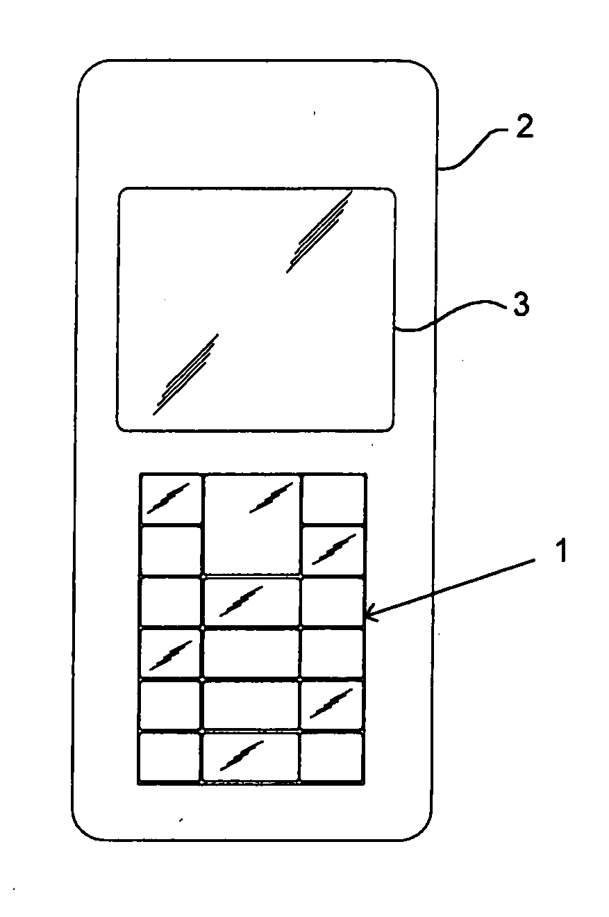
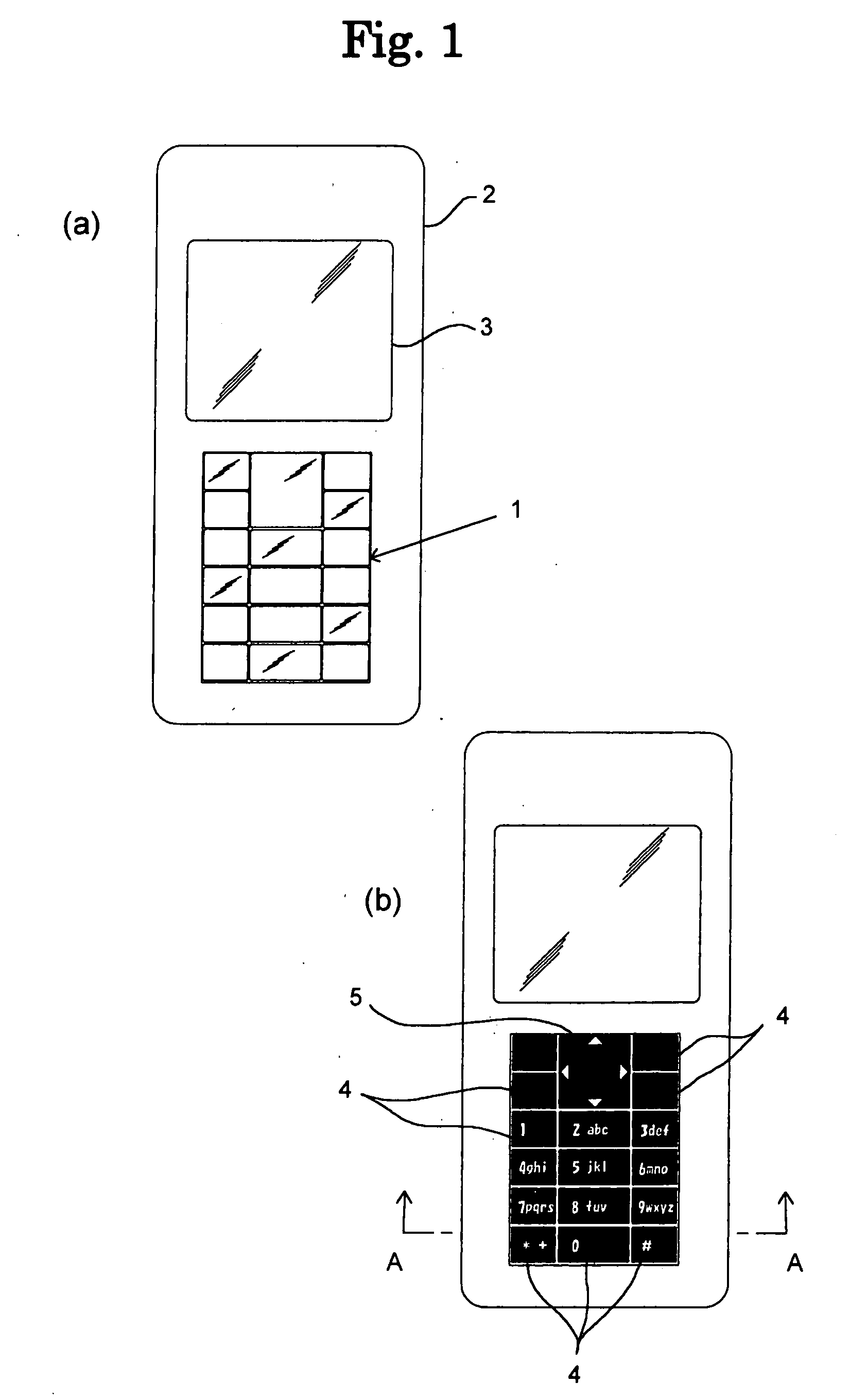
[0030]FIG. 1(a) is a view showing an example of a mobile telephone 2 incorporating a key sheet 1 of the present invention, and this view shows how the key sheet 1 looks when it is not illuminated. The mobile telephone 2, except for a liquid-crystal display screen 3 and a case portion, i.e., the entire surface of the key sheet 1, looks shiny in a metalic color such as lustrous silver or the like, and the characters, symbols or the like on the surface of each key are invisible.

[0031]FIG. 1(b) shows an illuminated state of the same key sheet 1 of FIG. 1, and numerals 0-9, alphabetic characters “a”-“z”, or symbols “*”, “+”, “#” marked in a reverse form on each of keytops 4 (state, in which characters or the like are visible with light being emitted from the surface of each key top 4 in the shape of characters or the like). The largest key is a “four-direction key with an enter key 5”. The key 5 has the enter key in the center and an arrow-marked (Δ) four-direction indicator key around ...

embodiment 2

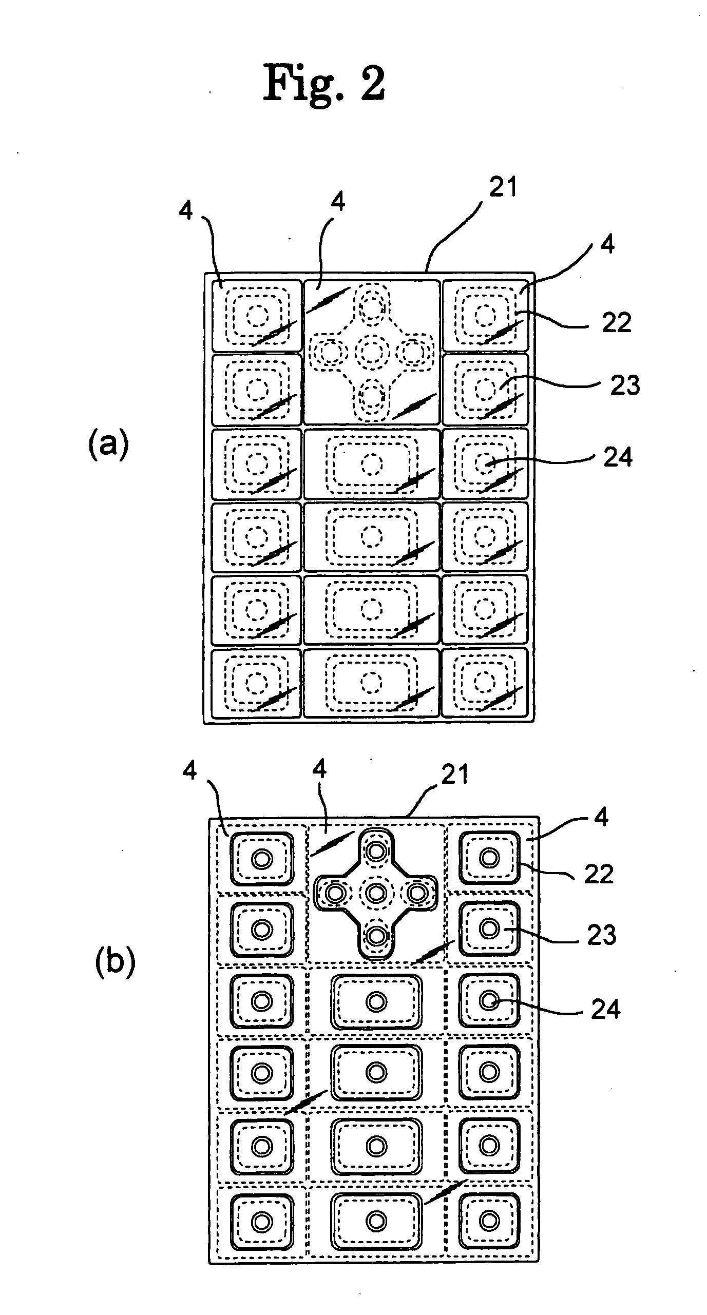
[0052] The embodiment of the present invention, shown in FIG. 1, can take various modifications or variations. The example shown in FIG. 5 is a second embodiment having all layers provided on an upper surface of the keytop 4. At first, a white undercoated layer 41 (solid color layer) is formed on the upper surface of the keytop 4, and then a reverse character (negative character) print layer 40 is formed on the undercoated layer 41 by screen printing.

[0053] When a colorless or colored translucent print layer 40a is further formed on the keytop, the reverse section 40a is filled with this material. A thin metal film (half mirror) 42 is formed on the translucent print layer 40a, and then a middle coat 43 and a topcoat 44 are sequentially formed to protect the surface. Additionally, a lower surface of a keytop 4 is bonded directly onto a keypad 23 via a transparent adhesive layer 27.

embodiment 3

[0054] The embodiment shown as an example in FIG. 6 is a third embodiment having all layers provided on a lower surface of a keytop 4. At first, the keytop 4 has been turned upside down and an undercoated layer 41 is provided on the lower surface, and then a reverse character print layer 40 is formed via a thin metal film (half mirror) 42. In the next place, a colorless or colored translucent print layer 40a is attached in the way that the reverse character portion is filled with the translucent material. The under surface of the keytop 4 is further bonded onto a keypad 23 via a transparent adhesive layer 27.

[0055] In this example, no layers are formed on the upper surface of the keytop 4. That is to say, there is no need to form a topcoat that undertakes surface protection of the keytop 4.


PUM


Abstract

A key sheet and a key top of novel design such that a character or a symbol cannot be recognized visually when not illuminated and can be recognized visually only when illuminated. In the key sheet comprising a key top for pressing a key and a key pad on which a plurality of key tops are placed in a matrix and which supports them integrally through transparent adhesive, the key top is composed of a transparent material, e.g. resin or glass, and provided with a metal thin film (half-silvered mirror) on the upper or lower surfaces. Consequently, a character or a symbol cannot be recognized visually when not illuminated and can be recognized visually only when illuminated.

Description

TECHNICAL FIELD [0001] The present invention relates to a key sheet and keytops of a new design used for devices having keytops of a push-button input type, such as a mobile telephone, personal data assistant (PDA), and personal computer or the like. The present invention is configured so that the surface looks like metallic-tone, and the characters, symbols or the like on the surface are made invisible in a non-illuminated condition, and the characters, simbols or the like on the surface are made visible by the transmitting light from an illumination light in an illuminated condition. BACKGROUND ART [0002] The foregoing key sheet is an assembly including a plurality of keytops (push buttons) and a sheet-like keypad. The key sheet is called an assembly because a plurality of the keytops are attached to the keypad by use of a transparent adhesive and both the keytops and the keypad can be integrally handled as a single assembly during the manufacture of devices. [0003] In general tec...

Claims


Application Information

Patent Timeline
IPC IPC(8): H01H13/14
CPCH01H13/704H01H13/83H01H2209/0021H01H2209/07H01H2221/07H01H2219/039H01H2219/06H01H2219/062H01H2219/03
Inventor KAMATA, YOSHITAKA
Owner SUNARROW CO LTD
Learn More