
Motor using working fluid distributed into chambers, which are provided for rotating rotors in opposite relative rotation directions

a working fluid and chamber technology, applied in the direction of liquid fuel engines, machines/engines, combination engines, etc., can solve the problems of increasing the relevant occupied space in the motor and the manufacturing cost, and achieve the effect of reducing energy loss, increasing the pressure of the line passage, and reliably rotating the inner-peripheral rotor forward

Inactive Publication Date: 2007-12-27
HONDA MOTOR CO LTD
View PDF8 Cites 7 Cited by
  • Summary
  • Abstract
  • Description
  • Claims
  • Application Information

AI Technical Summary

Benefits of technology

The present invention provides a motor that can vary the relative phase between the outer-peripheral rotor and the inner-peripheral rotor using a working fluid without increasing the size or number of parts of the motor. The motor includes an inner-peripheral rotor with permanent magnets and an outer-peripheral rotor with permanent magnets. A phase varying device is used to vary the relative phase between the inner-peripheral rotor and the outer-peripheral rotor. The device includes a forward-angle working chamber and a backward-angle working chamber for rotating the inner-peripheral rotor in a forward-angle direction and a backward-angle direction, respectively. A spur is used to control the distribution of the working fluid between the chambers, and an electromagnetic pressure control valve controls the pressure of the working fluid to control the position of the spur. This allows for a large amount of working fluid to be supplied without using a large-sized electromagnetic valve, and reduces the manufacturing cost and improves flexibility in controlling the phase variation.

Problems solved by technology

In addition, if an individual control mechanism using the electromagnetic valve or the like is provided to each working 1′; chamber, the number of necessary parts should be increased, thereby causing increases in a relevant occupied space in the motor and the manufacturing cost.

Method used


Image

  • Motor using working fluid distributed into chambers, which are provided for rotating rotors in opposite relative rotation directions
  • Motor using working fluid distributed into chambers, which are provided for rotating rotors in opposite relative rotation directions
  • Motor using working fluid distributed into chambers, which are provided for rotating rotors in opposite relative rotation directions

Examples


first embodiment

[0070]A first embodiment will be explained with reference to FIGS. 1 to 12.

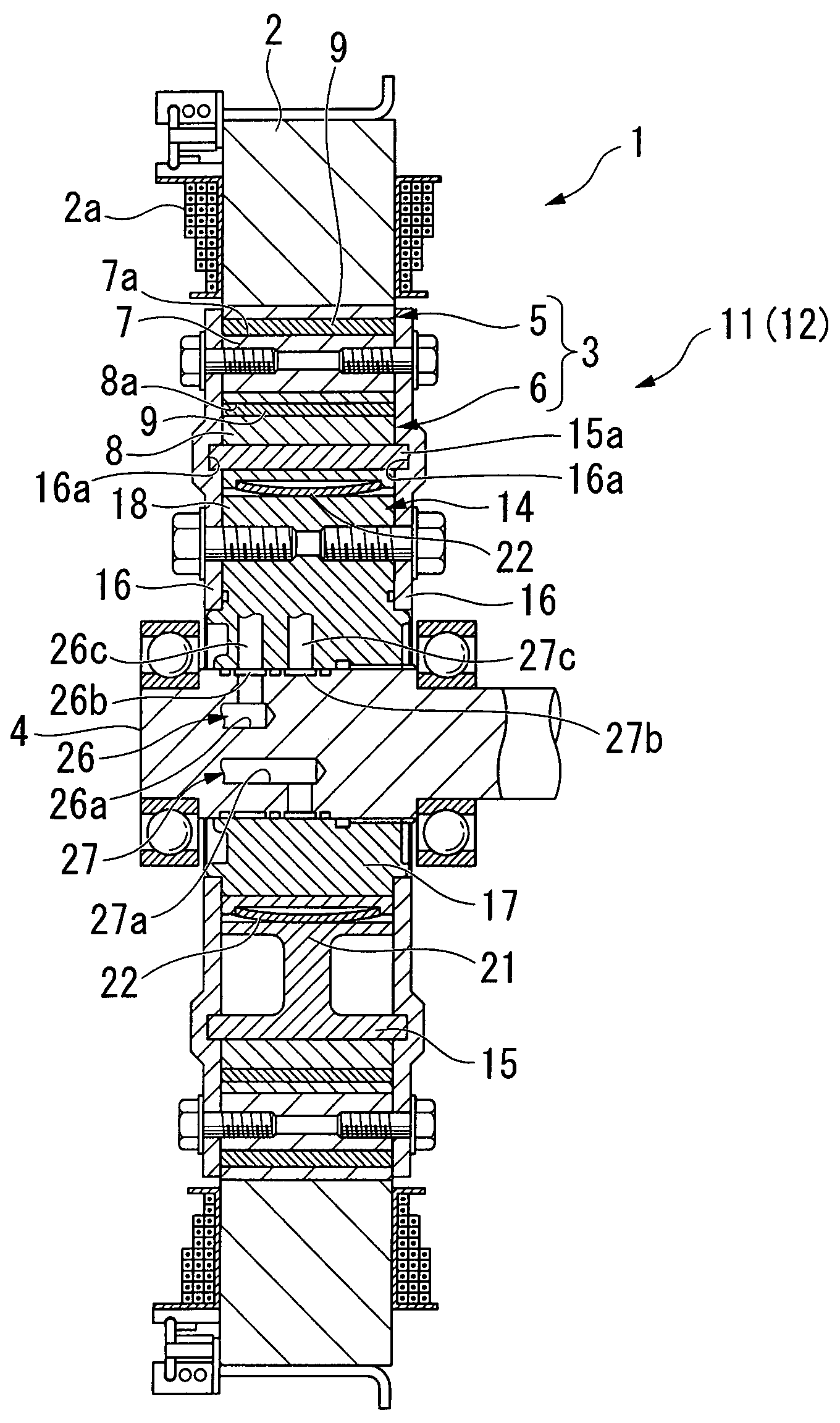
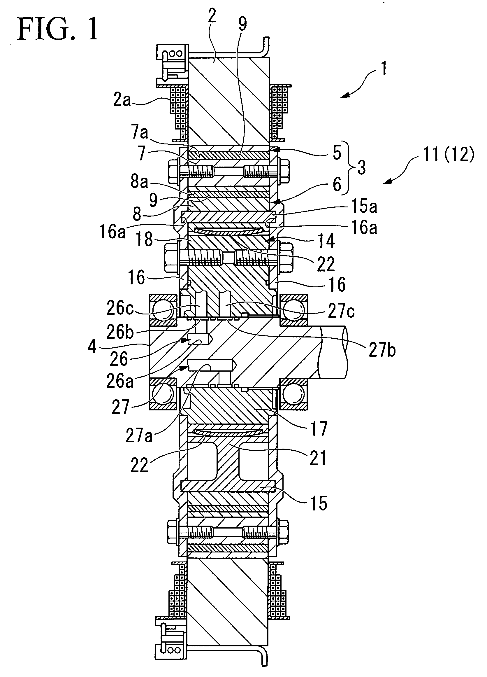
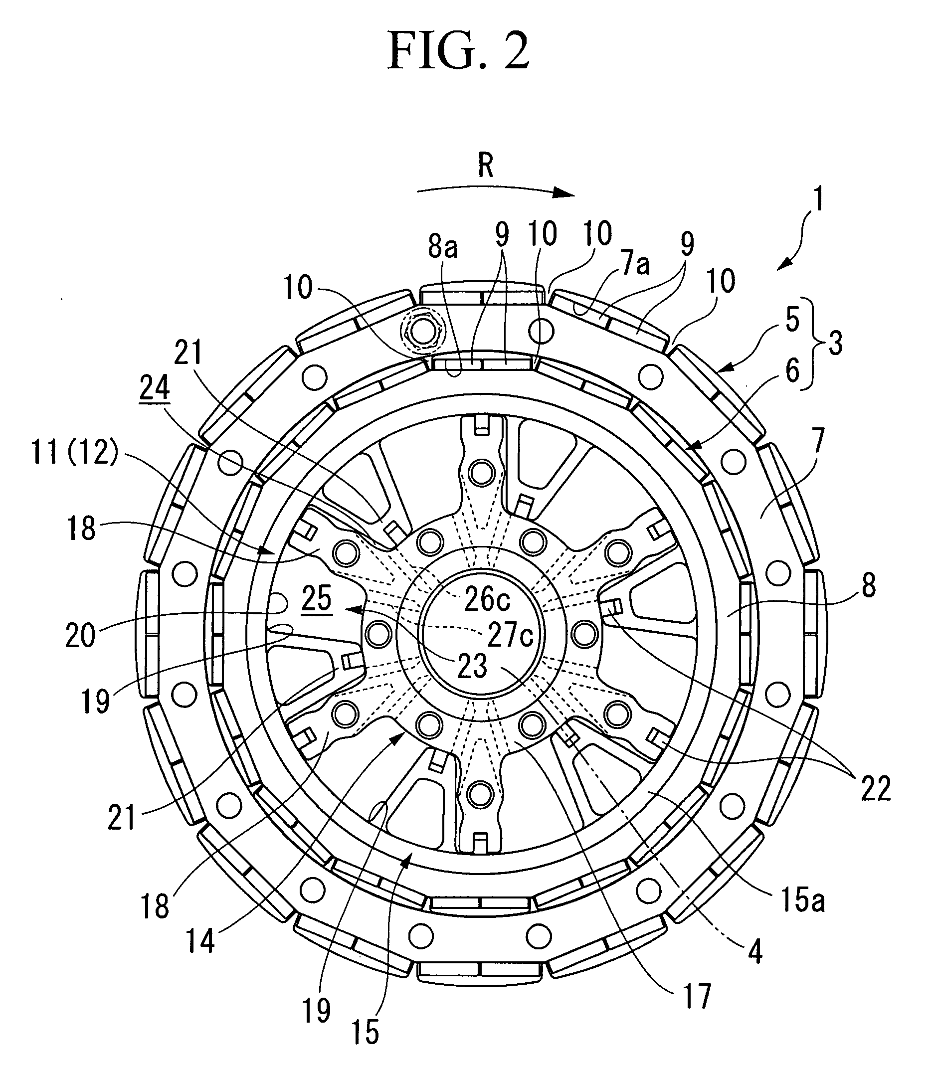
[0071]FIG. 1 is a sectional view of main parts of a motor 1 of the first embodiment. FIG. 2 is a side view (in which some parts are omitted) showing a rotor unit of the motor, which is controlled to stay at the most backward-angle position. FIG. 3 is an exploded perspective view showing the rotor unit of the motor. FIG. 4 is a side view showing the rotor unit, which is controlled to stay at the most forward-angle position.

[0072]As shown in FIGS. 1 to 4, the motor 1 is a blushless DC motor of an inner rotor type, in which a rotor unit 3 is arranged on the inner-peripheral side of a circular stator 2. The motor 1 may be used as a driving source for running a hybrid vehicle, a motor-driven vehicle, or the like. The stator 2 has stator windings 2a having different phases. The rotor unit 3 has a rotating shaft 4 on the axial center thereof.

[0073]When using the motor 1 as the driving source for running a vehicle, t...

third embodiment

[0133]FIG. 14 is a sectional view of main parts of a motor as the present invention. FIG. 15 is a side view showing a rotor unit of a motor as a fourth embodiment of the present invention.

[0134]The motors 1 of the third and fourth embodiments respectively have rotation mechanisms 111 and 211 (each belonging to the phase varying device 12), which are each different from the rotation mechanism 11 of the first embodiment. The other structural elements of each of the third and fourth embodiments are substantially identical to those of the first embodiment; thus, parts identical to those in the first embodiment are given identical reference numerals, and duplicate explanations are omitted.

[0135]The rotation mechanism 111 of the third embodiment, shown in FIG. 14, has (i) an inner cylindrical member 112 (i.e., a first member) which has a bobbin form, and is fit to the outer face of the rotating shaft 4 via splines in a manner such that the inner cylindrical member can rotate together with...

fourth embodiment

[0143]In the fourth embodiment shown in FIG. 15, a rotation mechanism 211 has (i) an inner block 212 (i.e., a first member), which is fit around the outer face of the rotating shaft 4 via splines, so that it can rotate together with the rotating shaft 4, and (ii) an outer block 213 (i.e., a second member), which has a substantially cylindrical form and arranged on the outer periphery of the inner block 212. The outer block 213 is fit and integrally fastened to the inner-peripheral face of the inner-peripheral rotor 6, and ends of the inner block 212 in the axial direction are integrally coupled with the outer-peripheral rotor 5 via drive plates (also as the first member, not shown), each striding over side ends of the outer block 213 and the inner-peripheral rotor 6. In this rotation mechanism 211, the inner block 212 is integral with the rotating shaft 4 and the outer-peripheral rotor 5, and the outer block 213 is integral with the inner-peripheral rotor 6.

[0144]The inner block 212...


PUM


Abstract

A motor includes inner-peripheral and outer-peripheral rotors which rotate coaxially and have permanent magnets along a circumference of each rotor; and a phase varying device for relatively rotating the rotors so as to vary a relative phase therebetween. The device has a forward-angle working chamber for relatively rotating the inner-peripheral rotor forward with respect to the outer-peripheral rotor, by using pressure of supplied working fluid; a backward-angle working chamber for relatively rotating the inner-peripheral rotor backward with respect to the outer-peripheral rotor, by using pressure of supplied working fluid; a passage switching valve for performing distribution with respect to supply and drainage of the working fluid between the working chambers in accordance with the position of a spur; and an electromagnetic pressure control valve for controlling pressure of the working fluid, and for controlling the position of the spur in the passage switching valve based on the controlled pressure.

Description

BACKGROUND OF THE INVENTION[0001]1. Field of the Invention[0002]The present invention relates to an (electric) motor having permanent magnets in a rotor, in particular, to a motor in which magnetic-field characteristics of the permanent magnets in the rotor are variable.[0003]Priority is claimed on Japanese Patent Application No. 2006-176296, filed Jun. 27, 2006, the content of which is incorporated herein by reference.[0004]2. Description of the Related Art[0005]In a known example of such a motor, an inner-peripheral rotor and an outer-peripheral rotor, each individually having permanent magnets, are arranged coaxially, and they are relatively rotated along a circumferential direction (i.e., the relative phase between the rotors is changed), so that the magnetic-field characteristics of the whole rotor are variable (see, for example, Japanese Unexamined Patent Application, First Publication No. 2002-204541).[0006]In this motor, in order to vary the relative phase between the inner-...

Claims


Application Information

Patent Timeline
Patent Type & Authority Applications(United States)
IPC IPC(8): H02K21/12F01C1/00
CPCF03C4/00H02K21/14H02K16/02H02K7/12
Inventor MASUDA, JUNNINOMIYA, RYO
Owner HONDA MOTOR CO LTD
Learn More