Position sensorless control apparatus for synchronous motor

a synchronous motor and control apparatus technology, applied in the direction of electronic commutators, motor/generator/converter stoppers, dynamo-electric converter control, etc., can solve the problems of high cost, low efficiency, and large vibration, and achieve low noise, less computation load, and high efficiency

Inactive Publication Date: 2007-12-27
DENSO CORP
View PDF26 Cites 21 Cited by
  • Summary
  • Abstract
  • Description
  • Claims
  • Application Information

AI Technical Summary

Benefits of technology

[0010]According to the present invention, since it is possible to supply power to a synchronous motor by sinusoidal wave, the synchronous motor can be driven at high efficiency and low noise. In addition, since the present invention requires less computation load than the conventional extended induced voltage method in which the induced voltage is calculated theoretically, control delay does not occur.

Problems solved by technology

However, the 120-degree induced voltage method has a problem in that, sine the idle period has to be provided, and the energization waveform is rectangular, efficiency is low and vibration is large.
However, since computation load is high, it has problem in that an expensive high-performance microcomputer is needed, and also man-hour are needed to adjust estimated gains and device constants.

Method used


Image

  • Position sensorless control apparatus for synchronous motor
  • Position sensorless control apparatus for synchronous motor
  • Position sensorless control apparatus for synchronous motor

Examples


Embodiment Construction

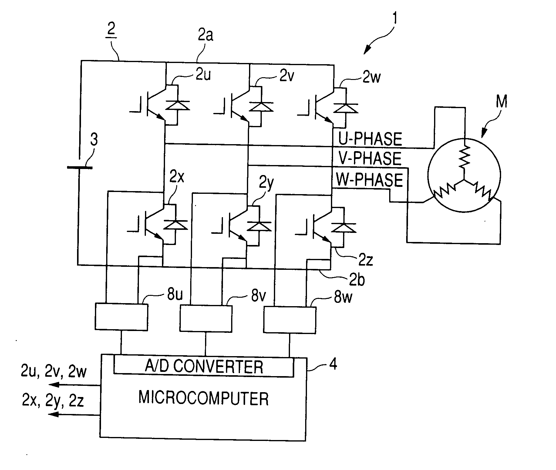
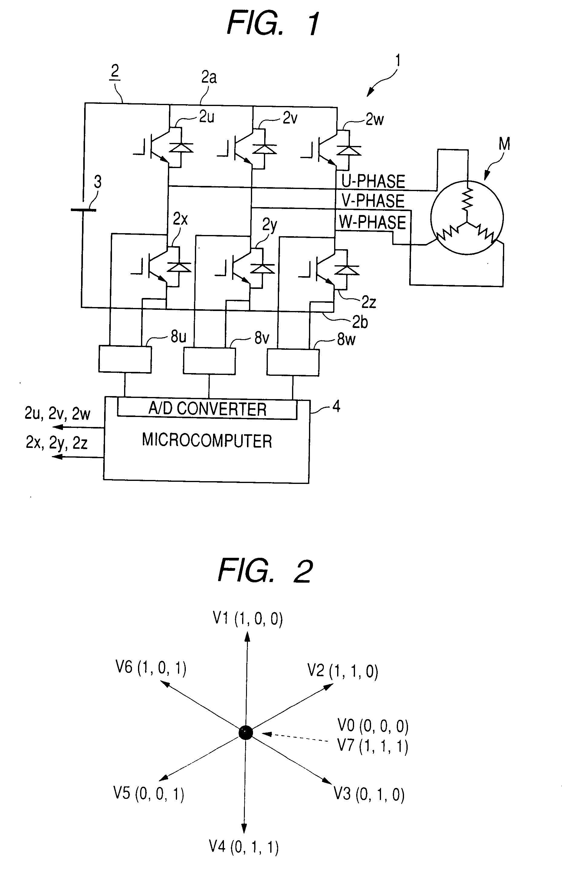
[0051]FIG. 1 is a circuit diagram showing an electrical structure of a synchronous motor control apparatus 1 according to an embodiment of the invention.

[0052]The synchronous motor control apparatus 1 is constituted by an inverter circuit 2, a DC power source 3, a microcomputer 4 including an A / D converter for detecting phases currents, and current detecting circuits 8u, 8v, 8w each constituted by an operational amplifier. The inverter circuit 2 supplies electric power to each of a U-phase, a V-phase, and a W-phase of a synchronous motor M having a permanent magnet rotor structure. The DC power source 3 supplies electric power to the inverter circuit 2. The microcomputer 4 generates a PWM signal having a duty ratio depending on an external command designating an inverter output voltage.

[0053]The inverter circuit 2 is a three-phase inverter circuit having a structure in which 6 power switching devices are bridge-connected between a DC bus 2a and a DC bus 2b. The 6 switching devices i...


PUM


Abstract

The position sensorless control apparatus is for controlling a synchronous motor having a permanent magnet rotor structure by generating fundamental voltage vectors used to designate on/off states of switching devices included in an inverter circuit thereof. The position sensorless control apparatus includes a current change rate detecting section detecting, as a current change rate, a change rate of a phase current flowing through the synchronous motor when a predetermined one of the fundamental voltage vectors is being generated, and a rotor magnetic pole position estimating section estimating, as a rotor magnetic pole position, a rotational position of a rotor of the synchronous motor on the basis of the current change rate detected by the current change rate detecting section.

Description

CROSS-REFERENCE TO RELATED APPLICATION[0001]This application is related to Japanese Patent Application No. 2006-163522 filed on Jun. 13, 2006, the contents of which are hereby incorporated by reference.BACKGROUND OF THE INVENTION[0002]1. Field of the Invention[0003]The present invention relates to a control apparatus for a synchronous motor, particularly relates to a position sensorless control apparatus capable of controlling a synchronous motor having a magnet rotor structure without using a position sensor for detecting a position of a magnetic pole of a rotor of the synchronous motor.[0004]2. Description of Related Art[0005]There are known various control methods for controlling a permanent magnet type synchronous motor without using a position sensor. One example is the one called “120-degree induced voltage method” in which the rotor magnetic pole position is estimated on the basis of an induced voltage zero-cross in a 60-degree idle period. Another example is the one called “...

Claims


Application Information

Patent Timeline
Patent Type & Authority Applications(United States)
IPC IPC(8): H02P1/46H02P6/06H02P6/08H02P6/18H02P6/182
CPCH02P6/182Y02P80/10
Inventor AOKI, YASUAKI
Owner DENSO CORP
Why Eureka
Try Eureka