Spatially-registered wavelength coding

a wavelength coding and wavelength technology, applied in the field of spatially registered wavelength coding, can solve the problems of incoherent source photon collection efficiency of incoherent sources, weak and spatially incoherent sources, and straightforward application of traditional spectroscopic techniques to spectral imaging

Active Publication Date: 2007-12-27
DUKE UNIV
View PDF5 Cites 20 Cited by
  • Summary
  • Abstract
  • Description
  • Claims
  • Application Information

AI Technical Summary

Benefits of technology

[0015] Another embodiment of the present invention is a system for spectrally imaging an object. The system includes a first dispersive element, a second dispersive element, a coded aperture, a detector, and a processor. The first dispersive element is located between the source object and the coded aperture. The second dispersive element is located between the coded aperture and the detector plane. Electromagnetic energy emanating from the source is passed through the first dispersive element and is imaged onto the co...

Problems solved by technology

Straightforward application of traditional spectroscopic techniques to spectral imaging, however, can be problematic.
Unfortunately, the sources tend to be weak and spatially-incoherent.
Slit-aperture dispersive spectrometers have extremely poor photon collection efficiency for incoherent sources.
As a result, a given spatio-spectral element tends to contain very few photons and h...

Method used


Image

  • Spatially-registered wavelength coding
  • Spatially-registered wavelength coding
  • Spatially-registered wavelength coding

Examples


Embodiment Construction

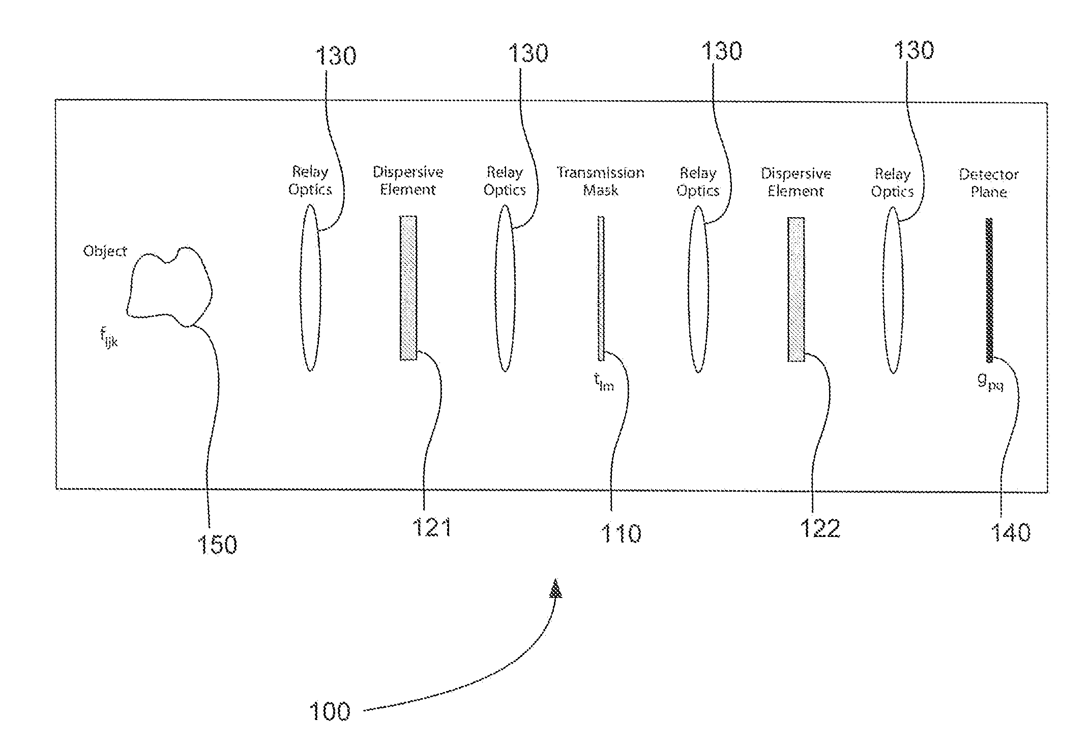
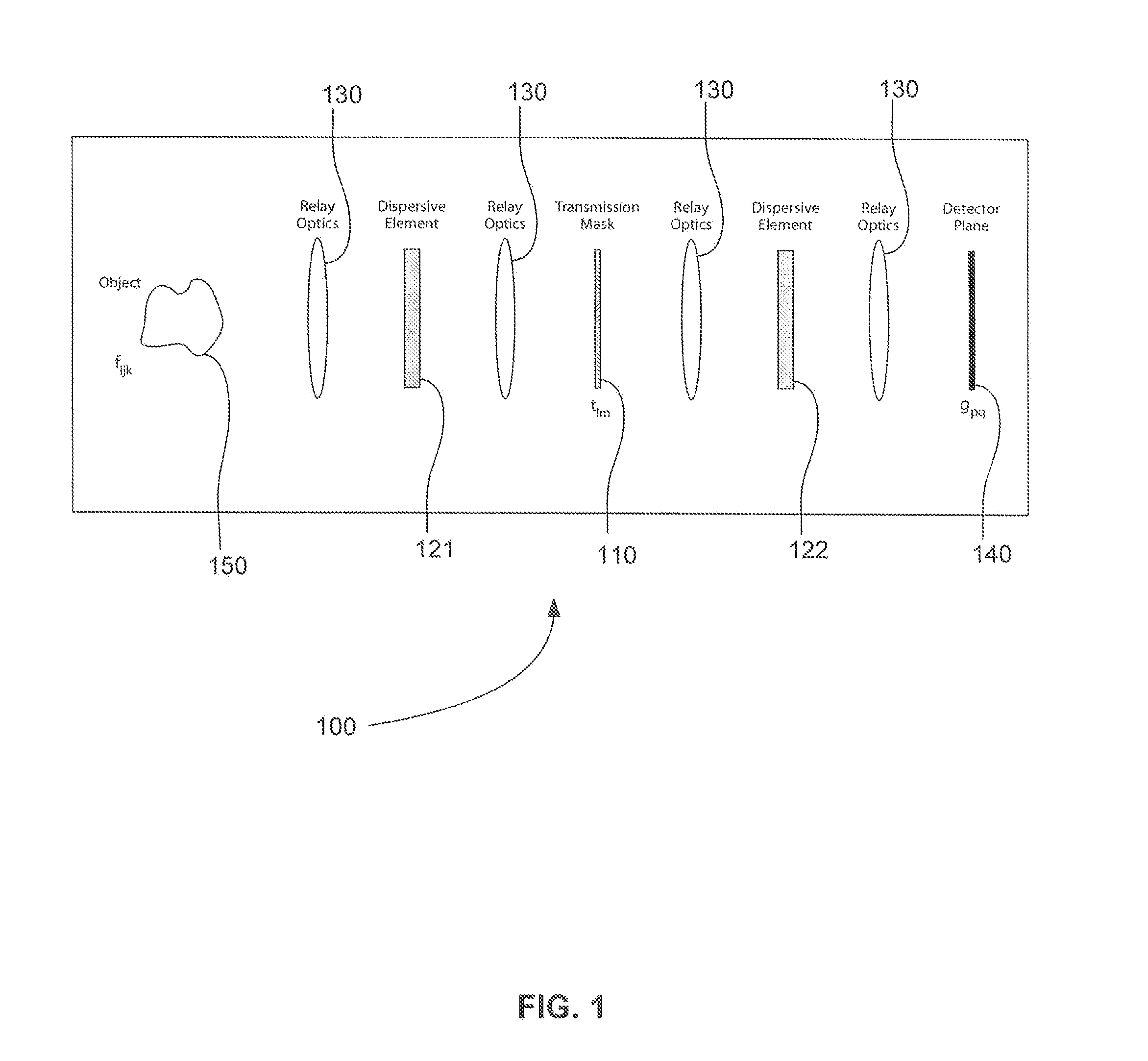
[0036] One embodiment of the present invention is system for using aperture coding techniques for implementing (spatially-varying) codes in the spectral structure of a source. The system includes a transmission mask and a pair of matched dispersive elements to produce a programmable spatio-spectral response.

[0037] An optical image is described by a spatial-spectral “datacube”ƒ(x,y,λ) describing the optical density at spatial position x,y and wavelength λ. Spectral imaging systems characterize the datacube or subsets thereof using interferometric, filter, or dispersive components.

[0038] Dispersive designs have the advantage of simple and robust physical implementation and programmable coding. In dispersive designs measurements take the general form

g(x,y)=∫t(x−λ,y)ƒ(x−λ,y,λ)dλ

where t(x,y) is a transmission mask or slit. In the case of computed spectral tomography, t(x,y)=1 and the direction of dispersion is rotated as a function of time. The common theme of these dispersive strate...


PUM


Abstract

Embodiments of the present invention relate to systems and methods for spectral imaging. Electromagnetic energy emanating from an object is passed through a first dispersive element, a coded aperture, and a second dispersive element to a detector plane. A wavelength-dependent shift is created by the first dispersive element. The coded aperture modulates the image emanating from the first dispersive element. The wavelength-dependent shift is removed from the modulated image by the second dispersive element producing a wavelength-independent image measured by the detector. A spectral image of the object is calculated from the measured image, a wavelength-dependent shift of the first dispersive element, the code of the coded aperture, and a wavelength dependent shift of the second dispersive element. A spectral image can be calculated from measurements obtained in a single time step and from a number of measurements that is less than the number of elements in the spectral image.

Description

CROSS-REFERENCE TO RELATED APPLICATION [0001] This application claims the benefit of U.S. Provisional Patent Application Ser. No. 60 / 792,335 filed Apr. 17, 2006, which is herein incorporated by reference in its entirety.BACKGROUND OF THE INVENTION [0002] 1. Field of the Invention [0003] Embodiments of the present invention relate to systems and methods for spectral imaging. More particularly, embodiments of the present invention relate to spectral imaging systems and methods in which a transmission mask and a pair of match dispersive elements are used to produce a spatio-spectral response within a single time step. [0004] 2. Background Information [0005] Traditional digital imaging techniques produce images with scalar values associated with each spatial pixel location in imaging spectroscopy, these scalar values are replaced with a vector containing the spectrum spectral information from that spatial location. The resulting datacube is, therefore, three-dimensional (two spatial dim...

Claims


Application Information

Patent Timeline
IPC IPC(8): G01J3/04
CPCG01J3/02G01J3/2846G01J3/2823G01J3/0229G01J2003/1213
Inventor BRADY, DAVID J.GEHM, MICHAEL E.
Owner DUKE UNIV
Why Eureka
Try Eureka