Method for manufacturing magnetic field detecting element utilizing diffusion and migration of silver

a magnetic field and detecting element technology, applied in the field of magnetic field detecting elements, can solve the problems of insufficient regularization of heusler alloy, inability to increase the annealing temperature far beyond, and limited overall magnetic field, and achieve the effect of reducing the regularization temperatur

Active Publication Date: 2007-12-27
TDK CORPARATION
View PDF2 Cites 10 Cited by
  • Summary
  • Abstract
  • Description
  • Claims
  • Application Information

AI Technical Summary

Benefits of technology

[0010]The object of the present invention is to provide a magnetic field detecting element that is used in a CPP-GMR head which allows reduction of regularization temperature. Another object of the present invention is to provide a method for manufacturing such a magnetic field detecting element.

Problems solved by technology

Further, since the magnetic moment of the outer pinned layer and that of the inner pinned layer cancel each other out, overall leakage of magnetic field is limited.
Because the temperature of the heat treatment is close to the upper limit temperature for ensuring that the nature of the shield layer is maintained, it is impossible to increase the annealing temperature far beyond the above-mentioned temperature if the Heusler alloy is used in the free layer and the pinned layer.
Consequently, the Heusler alloy is not sufficiently regularized, and it is impossible to fully exploit the nature of the Heusler alloy.

Method used


Image

  • Method for manufacturing magnetic field detecting element utilizing diffusion and migration of silver
  • Method for manufacturing magnetic field detecting element utilizing diffusion and migration of silver
  • Method for manufacturing magnetic field detecting element utilizing diffusion and migration of silver

Examples


1st embodiment

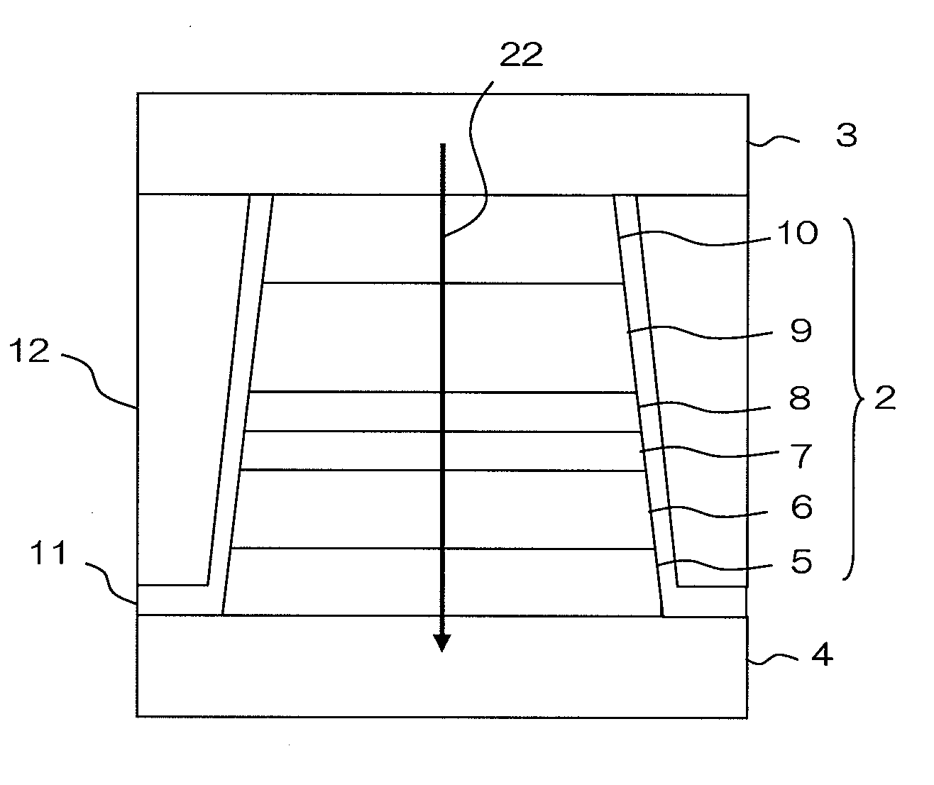
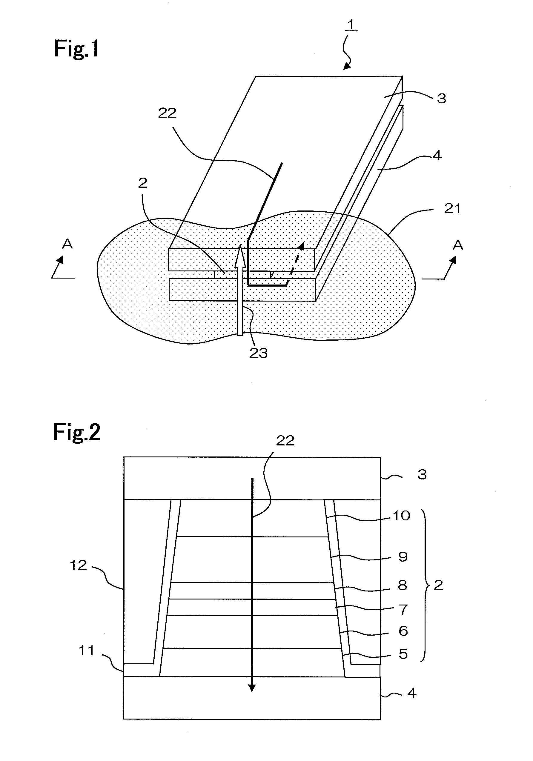
[0040]FIG. 2 is a side elevational view of the magnetic field detecting element, viewed from line A-A of FIG. 1, or viewed from the air bearing surface. The air bearing surface refers to the surface of thin-film magnetic head 1 that faces recording medium 21. Table 1 shows an exemplary layer configuration of thin-film magnetic head 1. Table 1 shows the layer configuration in the order of stacking, i.e., starting with buffer layer 5 in the bottom row, which is in contact with lower electrode / shield 4, ending with cap layer 10 in the top row, which is in contact with upper electrode / shield 3. In the description and tables, the numerals in the notation, such as Co70Fe30, represent atomic fractions (%) of elements. It should be noted that traces of other elements may be added as long as equivalent magnetic characteristics can be achieved. In other words, each layer does not have to be made of the elements which are indicated in the table.

TABLE 1Layer ConfigurationCompositionCap Layer 10...

2nd embodiment

[0045]Table 2 shows an exemplary layer configuration in which the above-mentioned structure of the free layer is also applied to the inner pinned layer. Inner pinned layer 73 has a stacked structure of Co70Fe30 / silver / Heusler alloy / 30Co70Fe. The Heusler alloy is made of, for example, Co2MnSi, but it may be made of a substance represented by the general composition X2YZ. The Heusler alloy may contain some remaining silver. Part of the silver in the silver layer is silver that has been diffused and that has migrated from the Heusler alloy layer in the same manner as described above. Instead of the silver layer, inner pinned layer 73 may contain a layer that is made of gold, copper, palladium, or platinum, or a layer that is made of an alloy containing at least two elements from among silver, gold, copper, palladium, and platinum. Similarly to the first embodiment, part of the metal(s) has been diffused and has migrated from the Heusler alloy layer.

TABLE 2Layer ConfigurationComposition...


PUM

PropertyMeasurementUnit
temperatureaaaaaaaaaa

Abstract

A method for manufacturing a magnetic field detecting element having a free layer whose magnetization direction is variable depending on an external magnetic field and a pinned layer whose magnetization direction is fixed with respect to the external magnetic field, said free layer and said pinned layer being stacked with an electrically conductive, nonmagnetic spacer layer sandwiched therebetween, wherein sense current is configured to flow in a direction that is perpendicular to film planes of the magnetic field detecting element is provided. The method has the steps of: forming a spacer adjoining layer that is adjacent to said spacer layer, Heusler alloy layer, and a metal layer successively in this order; and forming either at least a part of said pinned layer or said free layer by heating said spacer adjoining layer, said Heusler alloy layer, and said metal layer. The spacer adjoining layer has a layer that is chiefly made of cobalt and iron. The Heusler alloy layer includes metal which is silver, gold, copper, palladium, or platinum, or an alloy thereof. The metal layer is made of silver, gold, copper, palladium, or platinum, or an alloy thereof.

Description

[0001]The present application is based on, and claims priority from, J.P. Application No. 2006-173801, filed on Jun. 23, 2006, the disclosure of which is hereby incorporated by reference herein in its entirety.BACKGROUND OF THE INVENTION[0002]1. Field of the Invention[0003]The present invention relates to a magnetic field detecting element that is used in a hard disk drive, and more particularly to a method for manufacturing a magnetic field detecting element.[0004]2. Description of the Related Art[0005]Spin-valve-type GMR (Giant Magneto-Resistive) heads are known in the art as magnetic heads that meet requirements for high sensitivity and high output. A magnetic field detecting element that is used in a spin-valve-type GMR head comprises a free layer and a pinned layer that are stacked one on the other with a nonmagnetic spacer layer sandwiched therebetween. The free layer is a ferromagnetic material layer whose magnetization direction is variable depending on an external magnetic ...

Claims


Application Information

Patent Timeline
Patent Type & Authority Applications(United States)
IPC IPC(8): G11B5/012
CPCB82Y25/00Y10T29/49048G01R33/093G11B5/3906H01F10/1936H01F10/3272H01F41/304H01L43/08H01L43/10H01L43/12Y10T29/49039Y10T29/49046Y10T29/49043Y10T29/49025Y10T29/49044B82Y40/00H10N50/01H10N50/85H10N50/10
Inventor MIZUNO, TOMOHITOTSUCHIYA, YOSHIHIROSHIMAZAWA, KOJIHIRATA, KEIKAWAMORI, KEITA
Owner TDK CORPARATION
Why Eureka
Try Eureka