
High speed linear pick-and-place

Inactive Publication Date: 2008-01-03
SYSTATION SEMICON
View PDF12 Cites 20 Cited by
  • Summary
  • Abstract
  • Description
  • Claims
  • Application Information

AI Technical Summary

Benefits of technology

[0009]The present invention is a high-speed linear pick-and-place that can continuously feed semiconductor electronic devices to a machine vision inspection system or an electrical tester and consequently place them in at least two different sorted output locations without a substantial degradation of speed regardless of the sorting required.

Problems solved by technology

The main problem with conventional linear pick-and-places is the slow speed, particularly when accommodating inspection or test.
The walking beam type pick-and-place has slower product throughput because there is a return stroke after the part is placed, and during this time product doesn't progress forward in the production pipeline.
Another problem with the walking beam type pick-and-place is that the device needs to be set down on a surface and then picked up again by another vacuum nozzle.
The device can be damaged by setting it down.
Yet inspecting or testing the device on the nozzle further slows down the speed of the walking beam pick-and-place.
And finally, cumulative device-to-nozzle positional errors occur with additional handling (picking or placing) which adversely affects the accuracy of ultimate placement of the device into its destination.
The main problem with the gang type pick-and-place is that an array of many electronic devices are moved together and it is difficult to individually present the devices to a machine vision inspection system that needs to see each side of each device, or an electrical tester that requires the device to be individually plunged into a test station.
Another problem with the gang type pick-and-place is that the pitch between each pickup nozzle often needs to be changed real-time to adjust to the output media pitch, or non-real-time when preparing the machine to process other electronic devices from different media.
Also, sorting the electronic devices often slows down the overall throughput as the gang handler needs to move the entire array of nozzles to locations that only a few nozzles need to access.
Employing a plurality of nozzles is also expensive and more difficult to maintain.
And finally, stopping the gang pick-and-place for vision inspection or electrical slows down the machine as other devices are not being simultaneously processed.
The pick-and-places of the prior art are not ideally suited to accommodate vision inspection or electrical test and still maintain high speed handling.

Method used


Image

  • High speed linear pick-and-place
  • High speed linear pick-and-place
  • High speed linear pick-and-place

Examples


Embodiment Construction

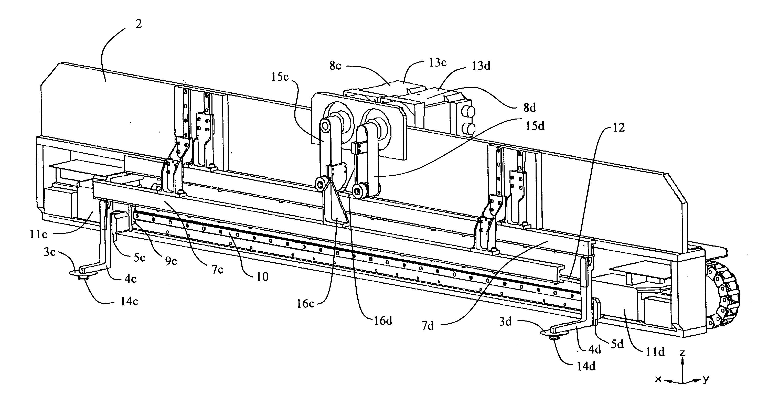
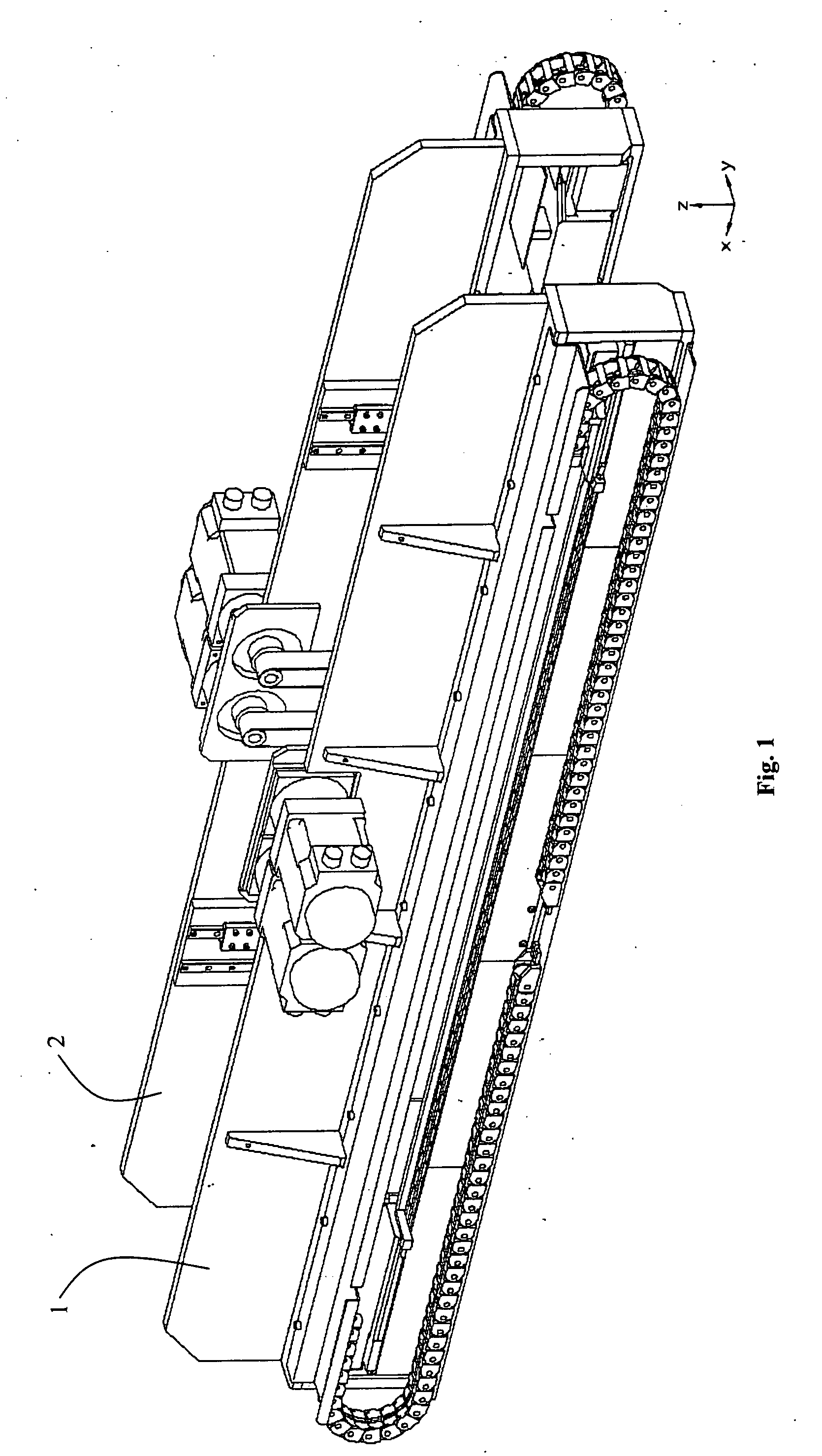
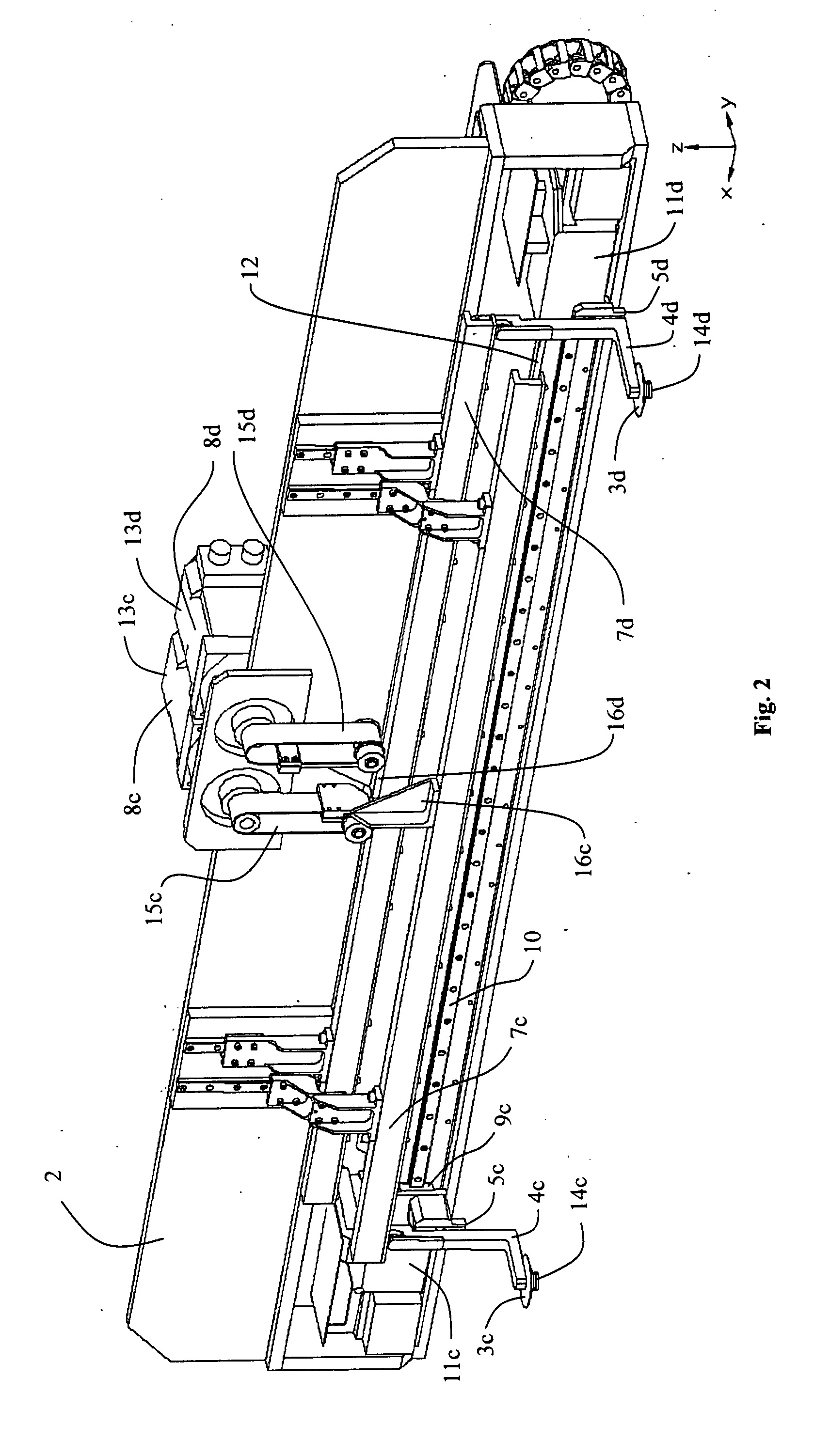
[0023]FIG. 1 illustrates the invention which comprises two identical linear pick-and-place assemblies 1 and 2. For clarity, FIG. 3 shows just linear pick-and-place assembly 2. The assembly has two subassemblies with independently positionable (in height (z) and horizontally (x)) vacuum pick-and-place nozzles 3c and 3d. The two assemblies are positioned (see FIG. 3) so that all 4 nozzles 3a, 3b, 3c, and 3d can all pick from common shared locations and place to other common shared locations and where all these locations share a common centerline. FIG. 3 shows the 4 nozzles at different heights. All the nozzles move in the same plane. Referring now to FIG. 2, each vacuum nozzle 3c and 3d has a surface 14c and 14d that contacts the electrical device. This surface has a hole to allow air to flow through. This hole is at times evacuated so that the device can be sucked onto the nozzle. Each nozzle is connected to an arm 4c and 4d which is connected to a dedicated vertical bearing 5c and 5...


PUM

PropertyMeasurementUnit
Lengthaaaaaaaaaa
Speedaaaaaaaaaa
Heightaaaaaaaaaa

Abstract

A high-speed linear pick-and-place for increasing the speed of transfer of semiconductor electronic devices with accommodation for automated inspection or test. The invention includes two or more linear pick-and-place assemblies, each having two or more independently positionable pick-and-place nozzles. These assemblies are aligned such that the 4 or more nozzles can all pick and place to common shared locations. The 4 or more nozzles are operated so that they can pass by each other on their return stroke, except that nozzles sharing a rail cannot pass each other.

Description

CROSS REFERENCE TO RELATED APPLICATIONS[0001]This application claims the benefit of provisional patent application Ser. No. 60 / 818,048 filed Jun. 30, 2006, by the present inventors.FEDERALLY SPONSORED RESEARCH[0002]Not Applicable.SEQUENCE LISTING OR PROGRAM[0003]Not Applicable.BACKGROUND—FIELD OF THE INVENTION[0004]The present invention relates generally to linear pick-and-places and more specifically it relates to a high-speed linear pick-and-places for increasing the speed of transfer of semiconductor electronic devices with accommodation for automated inspection or test. The invention is a high-speed linear pick-and-place that can continuously feed semiconductor electronic devices to a machine vision inspection system or an electrical tester and consequently place them in at least two different sorted output locations without a substantial degradation of speed regardless of the sorting required.BACKGROUND—PRIOR ART[0005]It can be appreciated that linear pick-and-places have been ...

Claims


Application Information

Patent Timeline
IPC IPC(8): B65G47/91
CPCB65G47/918
Inventor BEHNKE, MERLIN E.BERTZ, ROB G.JAHNKE, DUANE B.PICHLER, TODD K.PIKUS, KEN J.REILLY, MIKE J.ROLLMANN, DAVE J.SHIRES, MARK R.
Owner SYSTATION SEMICON
Learn More