Aircraft control system

Inactive Publication Date: 2008-01-03
AEROVIRONMENT INC
View PDF72 Cites 37 Cited by
  • Summary
  • Abstract
  • Description
  • Claims
  • Application Information

AI Technical Summary

Benefits of technology

[0011] The present invention addresses the needs mentioned above by providing an aircraft that can

Problems solved by technology

While these aircraft are quite noteworthy for their long term flight potential, they do have limits in their available power and payload.
However, due to high flexibility, the large aspect ratio and the constant chord, in-flight wing loads tend to cause the wing to develop a substantial di

Method used


Image

  • Aircraft control system
  • Aircraft control system
  • Aircraft control system

Examples


Embodiment Construction

[0023] The invention summarized above and defined by the enumerated claims may be better understood by referring to the following detailed description, which should be read in conjunction with the accompanying drawings. This detailed description of a particular preferred embodiment, set out below to enable one to build and use one particular implementation of the invention, is not intended to limit the enumerated claims, but rather it is intended to serve as a particular example thereof.

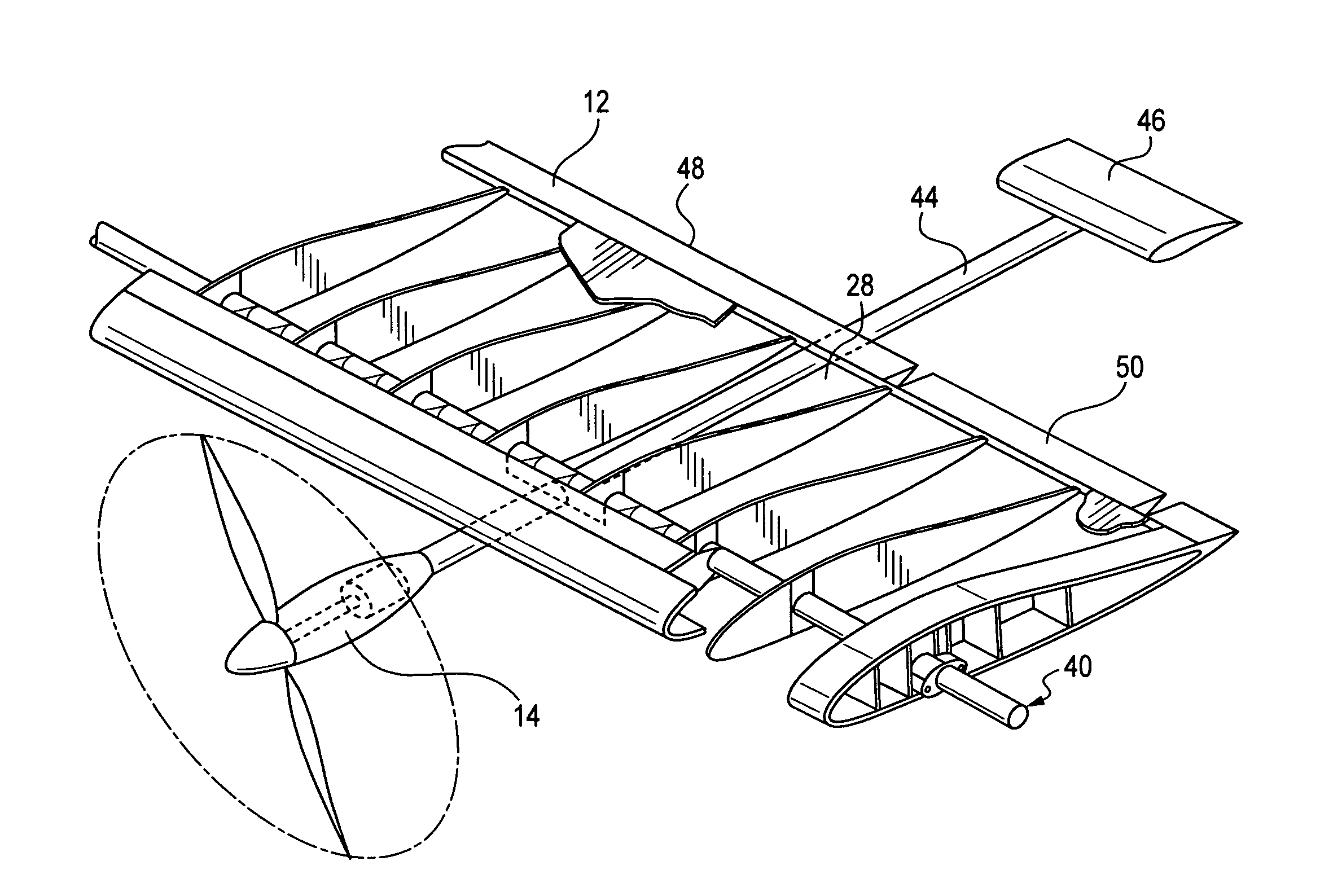
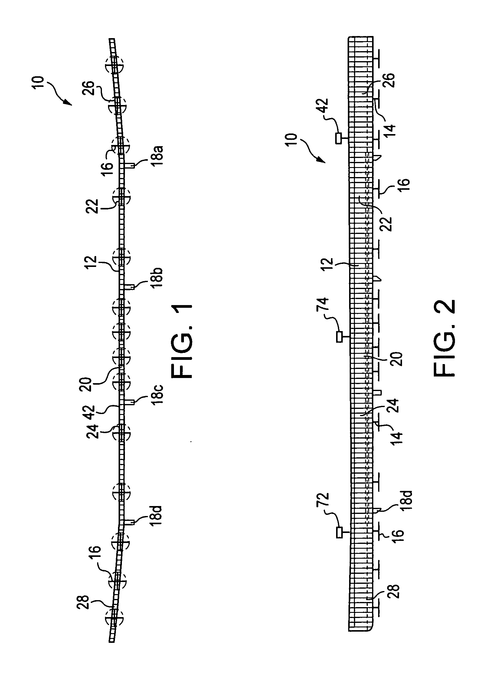
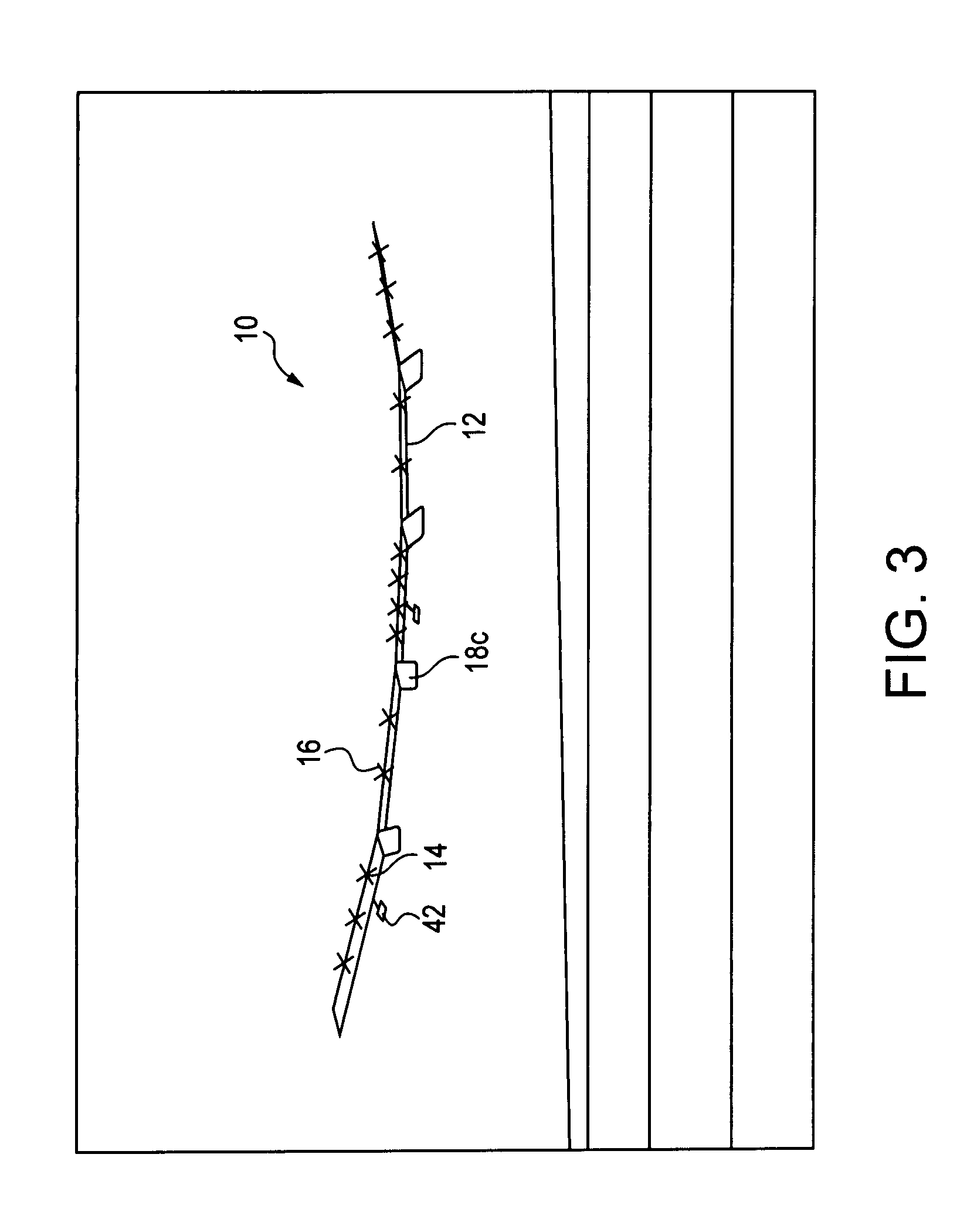
[0024] In accordance with the present invention, a number of preferred embodiments of an aircraft of the present invention are of designs similar to those of the Pathfinder, Centurion and / or Helios aircraft, as mentioned above in the Background of the Invention. While the embodiments' designs, and variations of them, are described below, further details useful for the practicing of this embodiment of the invention are provided in U.S. Pat. No. 5,810,284, which is incorporated herein by reference for...


PUM


Abstract

A span-loaded, highly flexible flying wing, having horizontal control surfaces mounted aft of the wing on extended beams to form local pitch-control devices. Each of five spanwise wing segments of the wing has one or more motors and photovoltaic arrays, and produces its own lift independent of the other wing segments, to minimize inter-segment loads. Wing dihedral is controlled by separately controlling the local pitch-control devices consisting of a control surface on a boom, such that inboard and outboard wing segment pitch changes relative to each other, and thus relative inboard and outboard lift is varied.

Description

[0001] The present invention relates to aircraft. More particularly, the present invention relates to aircraft having unique control mechanisms, and related methods of controlling an aircraft. The present application is a continuation in part of U.S. patent application Ser. No. 10 / 310,415, filed Dec. 5, 2002, which is a divisional application of U.S. patent application Ser. No. 09 / 527,544, filed Mar. 16, 2000, now abandoned, which claims priority from U.S. Provisional Patent Application Ser. No. 60 / 182,165, filed Feb. 14, 2000, each of which is incorporated herein by reference for all purposes. The present application is also a continuation in part of U.S. patent application Ser. No. 10 / 600,258, filed Jun. 20, 2003, which is a continuation in part of U.S. patent application Ser. No. 10 / 073,828, filed Feb. 11, 2002, now abandoned, which is a divisional of U.S. patent application Ser. No. 09 / 826,424, filed Apr. 3, 2001, now U.S. Pat. No. 6,550,717, issued Apr. 22, 2003, which claims p...

Claims


Application Information

Patent Timeline
IPC IPC(8): B64C13/00
CPCB64C3/42B64C3/38B64C15/02B64C17/00B64C39/024B64C39/10B64C2201/028B64C2201/042B64C2201/102B64C2201/122B64C2201/126B64C2201/127B64C2201/146B64C2201/165B64D27/24B64D31/06B64D2211/00H04B7/18504Y02T50/12Y02T50/145Y02T50/44Y02T50/69B64C3/52Y02T50/10Y02T50/50Y02T50/40B64U10/25B64U30/12B64U2101/20B64U2101/00B64U50/19B64U50/13B64U2201/20B64U2101/30
Inventor KENDALL, GREGLISOSKI, DEREK L.MORGAN, WALTER R.GRIECCI, JOHN A.
Owner AEROVIRONMENT INC
Why Eureka
Try Eureka