

Nonvolatile programmable resistor memory cell
- Summary
- Abstract
- Description
- Claims
- Application Information
AI Technical Summary
Benefits of technology
Problems solved by technology
Method used
Image

Examples
first embodiment
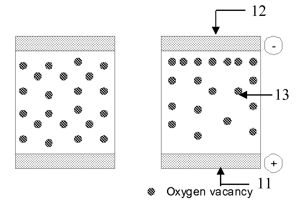
[0026]As shown in FIG. 1, the nonvolatile programmable resistor memory cell 10 according to this invention consists of a sandwich-type structure comprising a high-mobility oxygen ion conductor region 13 and two electrodes 11, 12.
[0027]An electrical signal applied to the electrodes 11, 12 causes migration of oxygen ions within the high-mobility oxygen ion conductor layer 13 towards the electrode (and vice versa). An applied voltage thus alters the oxygen ion concentration in the vicinity of the electrodes and hence the energy barriers for charge carrier injection and therefore the resistance of the memory cell. The interface region near the electrodes can be reversibly switched between two or more resistance states associated with migration of oxygen ions.
second embodiment
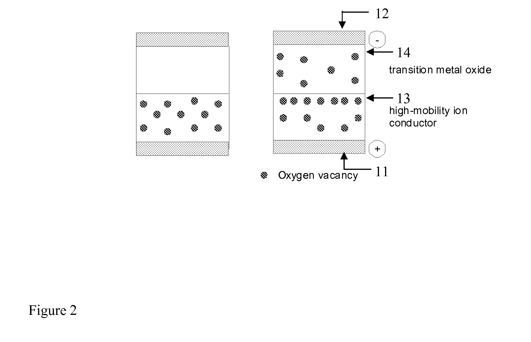
[0028]FIG. 2 of the accompanying drawings depicts this invention. The memory cell 10 according to this embodiment is a sandwich-type structure comprising a high-mobility oxygen ion conductor region and a transition-metal oxide region 14 that exhibits a filling-controlled metal-insulator transition, and two electrodes 11, 12. An electrical signal applied to the electrodes causes migration of oxygen ions from the high-mobility oxygen ion conductor region 13 into the transition-metal oxide region 14 (and vice versa). This changes the formal oxidation state of the transition metal ion in the transition-metal oxide layer and concomitantly the filling of the transition metal band. The initial doping level of the transition-metal region can be chosen such that a significant change of the resistance of the transition-oxide metal oxide layer is obtained for a small change in oxygen stoichiometry. Therefore the resistance of the memory cell can be reversibly switched between two or more resis...
PUM
 Abstract
Description
Claims
Application Information