Printhead, head cartridge, and printing apparatus employing either of same

a printing apparatus and cartridge technology, applied in the direction of printing, digital output to print units, printing, etc., can solve the problems of increased size of the apparatus, increased cost, and noise generated by the current, so as to reduce the number of input pads and minimize the increase in size and cost of the apparatus.

Inactive Publication Date: 2008-01-03
CANON KK
View PDF4 Cites 1 Cited by
  • Summary
  • Abstract
  • Description
  • Claims
  • Application Information

AI Technical Summary

Benefits of technology

[0021]A printhead, a head cartridge, or a printing apparatus in which either is used according to this invention is capable of minimizing increased

Problems solved by technology

However, there are problems such as the fact that due to shortening that cycle, many signals are transmitted with high frequency, and thus there is an effect from radiated electromagnetic waves.
Also, in a thermal inkjet printing apparatus, in addition to a signal, a high current that is allowed to flow to a heater flows to the printhead by being transmitted through a long flexible cable or the like from the main body of the printing apparatus,

Method used


Image

  • Printhead, head cartridge, and printing apparatus employing either of same
  • Printhead, head cartridge, and printing apparatus employing either of same
  • Printhead, head cartridge, and printing apparatus employing either of same

Examples


example 1

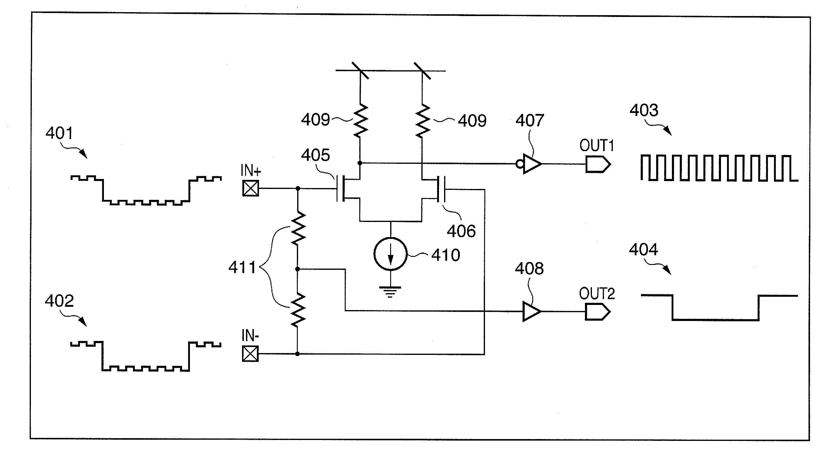
[0062]Following is a description of the differential input circuit and differential signal used in this example, provided in the form of an element substrate, with reference to the example in FIG. 7. The differential input circuit is configured from resistors 409 and 411, MOSs 405 and 406, a constant current source 410, and buffers 407 and 408. In an input signal, a low voltage differential signal (a double-ended pulse signal) has been superimposed on a single-ended pulse signal. As shown in FIG. 6, in a signal 401, a signal A+ has been superimposed on a signal B, and in a signal 402, a signal A− has been superimposed on the signal B.

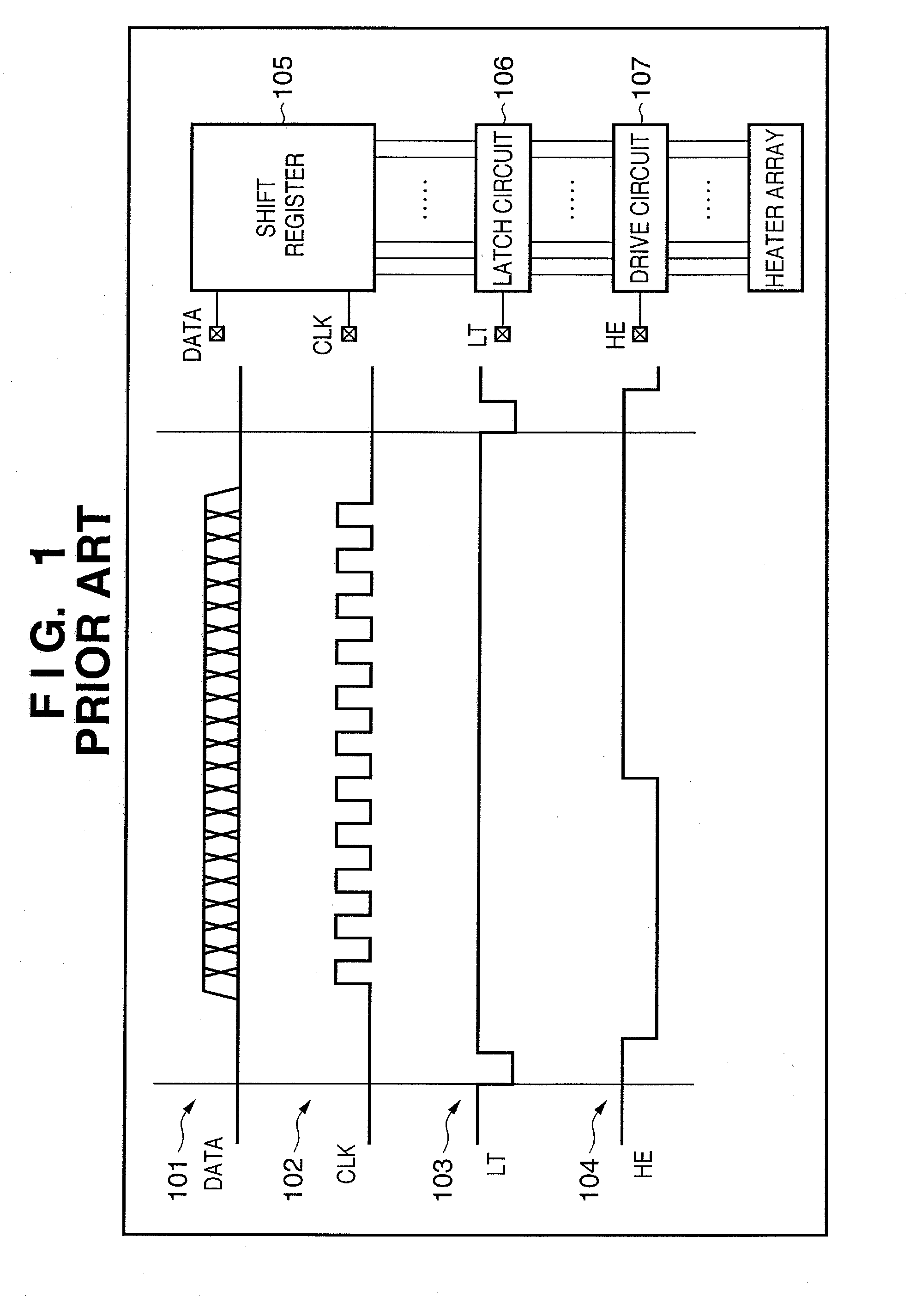
[0063]Electrothermal transducers are provided on the element substrate of the invention, and a shift register and a latch circuit that are logic circuits for selectively driving the electrothermal transducers, and a drive circuit and the like, are provided on the element substrate. The printhead performs printing based on the image data, and the image d...

example 2

[0082]In this example, unlike in Example 1, a configuration is provided in which the differential input circuit and the logic circuit are on the same substrate.

[0083]FIG. 10 is a block diagram showing the characteristics of Example 2 of the invention.

[0084]In this example, the data and timing charts of that data are the same as in Example 1, so a description thereof is omitted here.

[0085]The logic circuit 504 includes a heater array constituting a printing element and a drive circuit for the heater array, a latch circuit, and a shift register, and on the same substrate 502, the same differential input circuit 503 as in Example 1 is configured. The hysteresis output configuration shown in FIG. 11 may be adopted for a portion of an LT signal output stage in a circuit structure that is subjected to logic reversal due to noise.

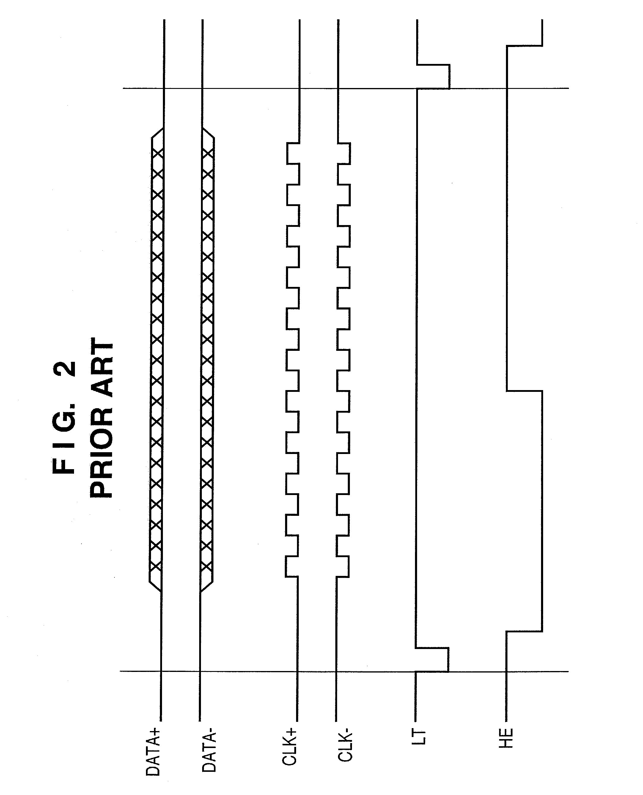
[0086]In the above manner, in this example, it is possible to reduce the six input pads from the DATA+ signal, the DATA− signal, the LT signal, the CLK+ signal, t...


PUM


Abstract

A printhead that minimizes increased size and cost of an apparatus by reducing a number of input pads, while making use of the advantages of employing a differential input circuit. This printhead has an input pad to which a differential signal obtained by superimposing two or more logic signals is input. The differential input circuit includes a circuit that disassembles the differential signal input via the input pad into separate logic signals.

Description

BACKGROUND OF THE INVENTION[0001]1. Field of the Invention[0002]The present invention relates to a printhead, a head cartridge, and a printing apparatus employing either of the printhead and the head cartridge, suitable for use in inkjet printing in which ink droplets are discharged.[0003]2. Description of the Related Art[0004]An inkjet printing apparatus is configured so as to print information on a print medium by discharging printing ink from a plurality of fine nozzles of a printhead according to a print signal. An inkjet printing apparatus has advantages such as being capable of non-contact printing to a print medium such as print paper, easy conversion to color, and being abundantly quiet.[0005]FIG. 1 is a block diagram showing a circuit configuration in a conventional printhead, and an example timing chart of signals transmitted to the printhead from a printing apparatus.[0006]A DATA signal 101 (digital signal: image data) is serially input to a shift register 105 in synchron...

Claims


Application Information

Patent Timeline
IPC IPC(8): B41J29/38
CPCB41J2/04518B41J2/04521B41J2/0458B41J2/04541B41J2/04523B41J2/01G06F3/12
Inventor KASAI, RYOSAKURAI, MASATAKA
Owner CANON KK
Why Eureka
Try Eureka