Method and apparatus for automatic gas control for a plasma arc torch

a plasma arc torch and gas control technology, applied in plasma welding apparatus, plasma technique, manufacturing tools, etc., can solve the problems of increasing control difficulties, tedious empirical determinations of different torches, and wear of consumable parts, so as to prolong the life of the electrode, increase the cut duration, and increase the ramp down time

Active Publication Date: 2008-01-10
HYPERTHERM INC
View PDF99 Cites 11 Cited by
  • Summary
  • Abstract
  • Description
  • Claims
  • Application Information

AI Technical Summary

Benefits of technology

[0015] The method can also include the step of extending the life of a consumable (such as an electrode or a nozzle) by controlling a ramp-up flow of the plasma gas during start-up of the torch using the programmable control valve, especially when the current flow is transferred from the nozzle to the workpiece. It can also include the step of controlling a ramp-down flow of the plasma gas during shut-down of the torch using the programmable control valve, which can also extend the life of the consumable. In some embodiments, both the ramp-up flow of the plasma gas and the ramp-down flow of the plasma gas are controlled using the programmable control valve. This can be used to reduce the cycle time of workpiece cuts by the torch, thereby increasing production line throughput and capacity. In some embodiments, the torch consumable either is or includes an electrode and operation of the torch includes controlling at least one of a ramp-up or a ramp-down of a flow of the plasma gas based on a type of the electrode installed in the torch, i.e., some electrodes perform better and / or last longer when start-up and / or shutdown is accompanied by a customized plasma gas flow curve.
[0017] The programmable control valve can be directly coupled to the torch body of the torch, e.g., such that there is no hose length between the valve and the torch. In some embodiments, at least a portion of the programmable control valve is disposed within the torch. The method can also the step of increasing a ramp down time of the flowing first gas to prolong a life of the electrode. This ramp down time can be increased based on, e.g., an increased cut duration of the torch or a higher operating current level of the torch. In some embodiments the ramp down time interval can be decreased to increase the electrode life, e.g., when the torch is being used to make short duration cuts.
[0018] The method can also include a vent valve for venting the plasma gas (e.g., to atmosphere), which can be used to decrease the amount of time required to vent the plasma gas, e.g., at the end of a cutting cycle. The vent valve can be a programmable control valve, such as a proportional solenoid control valve. In some embodiments the vent valve can include two or more on-off solenoid valves that are mounted in parallel.
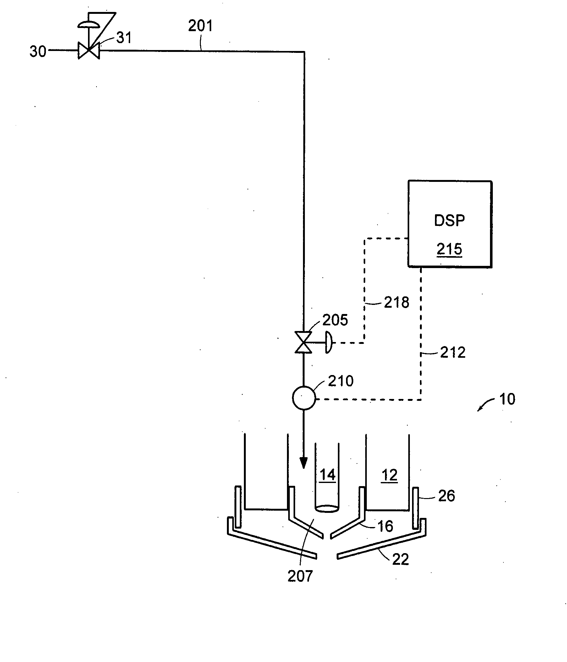
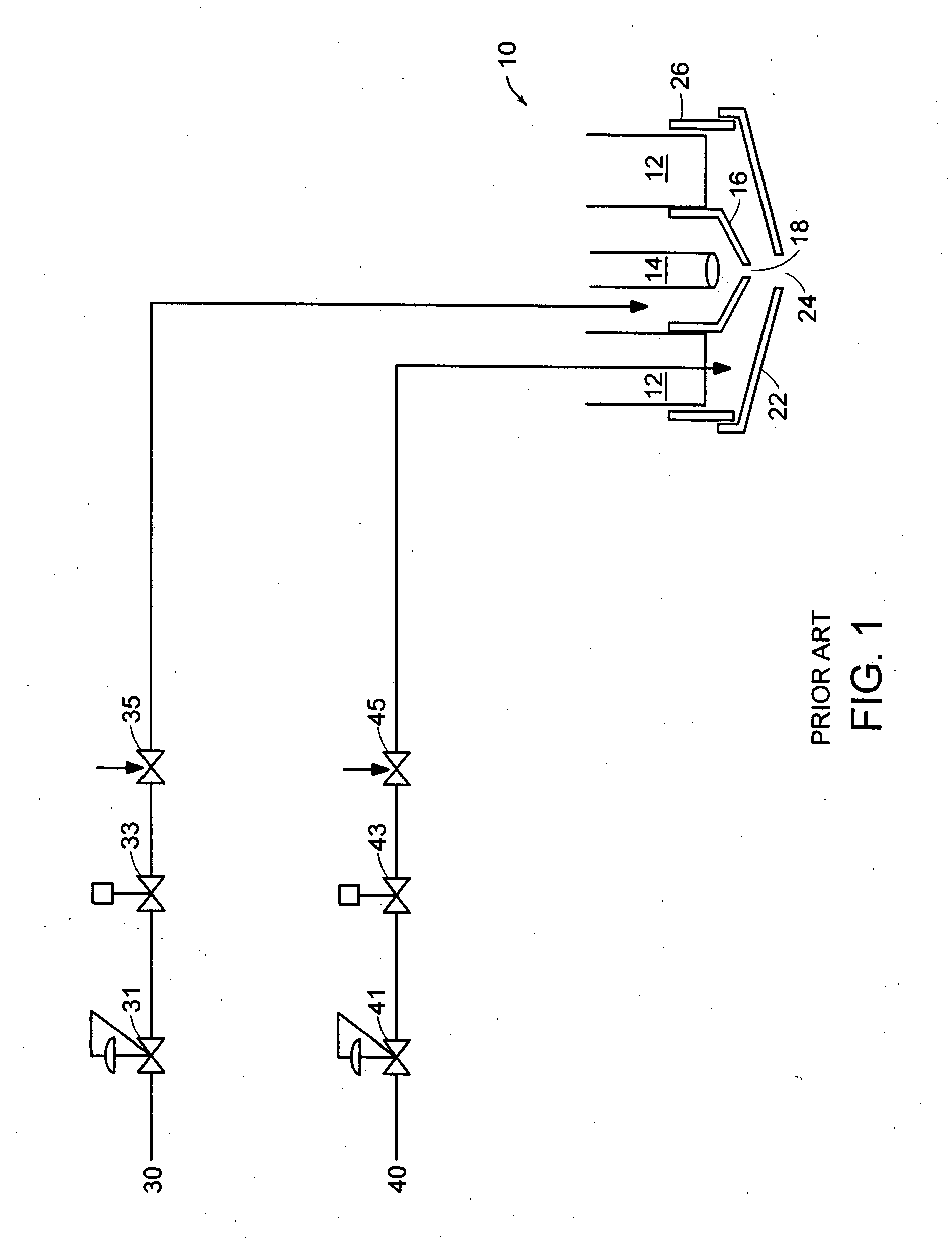
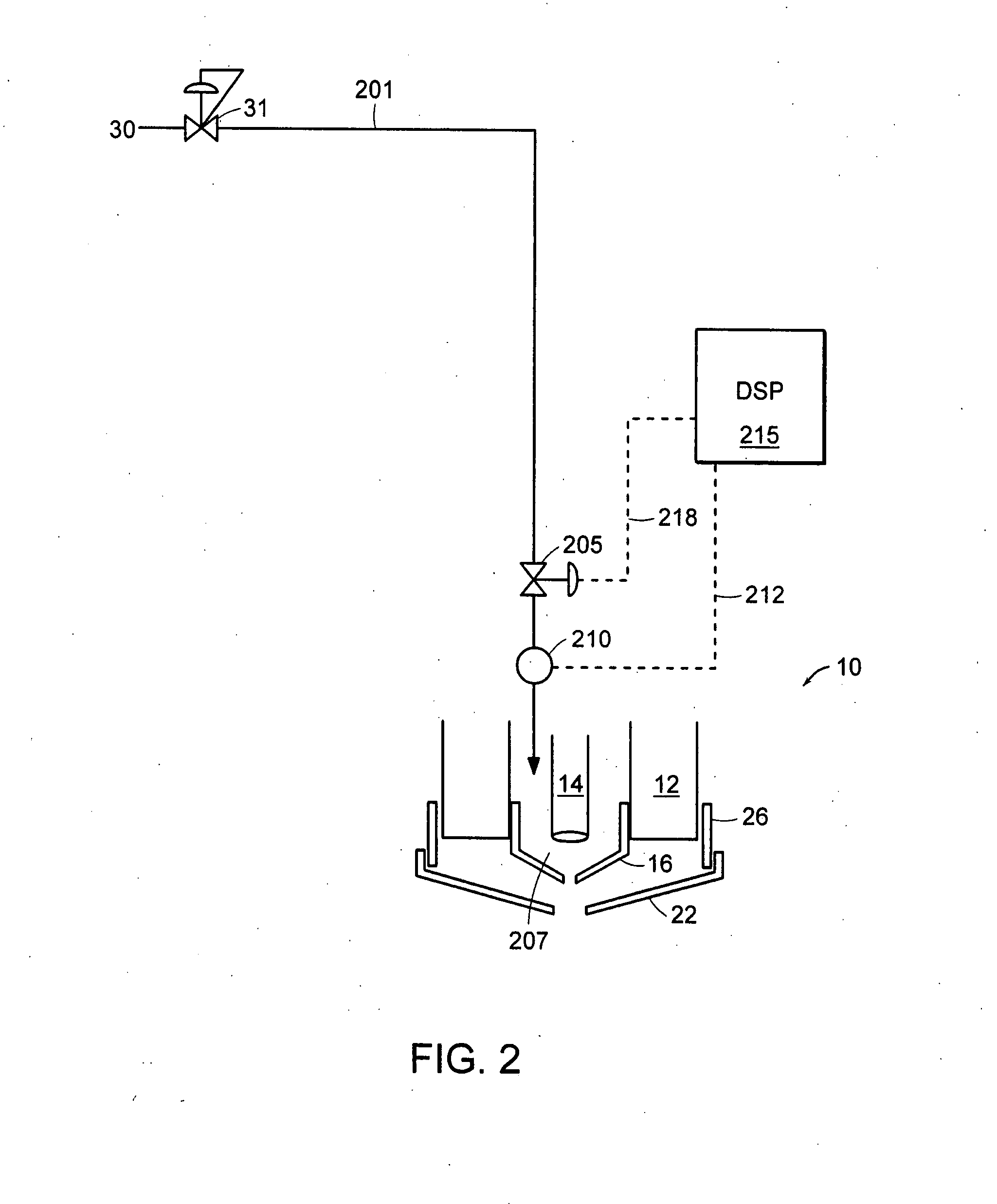
[0019] This method can also include positioning a second programmable control valve in a second fluid line, which can be used to supply a second gas to the torch. The first gas can be a plasma gas and the second gas can be a shield gas, and the flow of the second gas can cool and protect from splatter a shield that surrounds a nozzle and is mounted on the torch body. The method can also include diverting at least a portion of the flow of the second gas (e.g., a shield gas) through a third fluid line to join with the flow of the plasma gas to the torch. A third programmable control valve can be positioned in the third fluid line adjacent the torch, to control the diverted shield gas flow. The third programmable control valve can be manipulated to control the flow of the diverted portion of the second gas and to compensate for a volume in the third fluid line between the third programmable control valve and the torch. In another embodiment, the method can include diverting at least a portion of the flow of the plasma gas through a third fluid line to join with the flow of the second gas (e.g., the shield gas) to the torch. The third programmable control valve can be positioned in the third fluid line adjacent the torch to control the diverted plasma gas flow. The third programmable control valve can be manipulated to control the flow of the diverted portion of the plasma gas and to compensate for a volume in the third fluid line between the third programmable control valve and the torch.
[0021] The method can also include the step of adjusting the flow of the first gas (e.g., a shield gas) to reduce formation of a divot in an interior cut of a workpiece, to control slag formation, and / or to improve the quality of a corner cut within a workpiece. Embodiments include controlling the flow of the shield gas to be a piercing flow during a piercing operation of the torch (e.g., when initially penetrating a workpiece), or to be a cutting flow during a cutting operation of the torch (such as during a prolonged cutting operation).

Problems solved by technology

During operation of the torch, certain consumable parts become worn and have to be replaced.
Unfortunately, there are drawbacks associated with these different approaches.
Such tedious empirical determinations were performed for different torches, systems, consumable sets, and cutting conditions.
These control difficulties are exacerbated by the rapid system dynamics, which can all take place within a time span of about 300 milliseconds or less.
The determination of the proper hose length and current ramp down characteristics to achieve an acceptable termination gas flow profile is empirically acquired and is extremely time consuming.
Similar developmental problems are encountered when customizing the gas flow characteristics required for optimal use of the '494 patent, e.g., while transferring the current from the nozzle to the workpiece.
Performance of such swirl rings can also be adversely affected, e.g., by varying gas supply pressures and other gas flow parameters.
Finally, considering the gas distribution feed system of the '043 patent, the multiple flow channels for each gas stream are complex and require many component parts.

Method used


Image

  • Method and apparatus for automatic gas control for a plasma arc torch
  • Method and apparatus for automatic gas control for a plasma arc torch
  • Method and apparatus for automatic gas control for a plasma arc torch

Examples


Embodiment Construction

[0039]FIG. 2 is a schematic representation of a plasma gas supply system to a plasma arc torch incorporating features of the invention. A plasma gas, e.g., including oxygen, nitrogen, and / or argon flows from a plasma gas supply 30 to a plasma gas supply line 201. This first gas supply line channels plasma gas to the plasma torch 10 through a programmable control valve 205 such as a proportional solenoid control valve. The plasma gas flows to a plasma chamber 207 of the torch, and can pass through a sensor 210, such as a flow sensor or a pressure sensor. In some embodiments a signal 212 from the plasma gas sensor 210 can pass to a digital signal processor (DSP) 215 (e.g., a microprocessor, computer, computerized numeric controller (CNC), or PLC), which in turn can manipulate an output 218 to the programmable control valve 205 based on the signal 212. However, the sensor 210 is optional and embodiments include a plasma gas supply line 201 with no sensor 210, and manipulation of the ou...


PUM

PropertyMeasurementUnit
distanceaaaaaaaaaa
distanceaaaaaaaaaa
distanceaaaaaaaaaa

Abstract

A method and apparatus for controlling a gas supply to a plasma arc torch uses a proportional control solenoid valve positioned adjacent the torch to manipulate the gas flow to the torch, thereby extending electrode life during arc transfer and shutdown. Swirl ring design can be simplified and gas supply and distribution systems become less complicated. The invention also allows manipulation of shield gas flow to reduce divot formation when making interior cuts. The system can be controlled with a digital signal processor utilizing a feedback loop from a sensor.

Description

RELATED APPLICATIONS [0001] This application is a continuation-in-part of U.S. Ser. No. 11 / 045,012, filed on Jan. 27, 2005, the contents of which are incorporated herein by reference. This application claims benefit of and priority to U.S. Ser. No. 11 / 045,012.FIELD OF THE INVENTION [0002] The invention relates generally to plasma arc cutting torches, and more particularly to control systems and methods for controlling gas supplies to such torches to enhance their operation. BACKGROUND OF THE INVENTION [0003] Plasma arc cutting torches have a wide variety of uses, such as the cutting of aluminum sheet metal, thick plates of steel or stainless steel, or thin sheets of galvanized metal. As illustrated in FIG. 1, a plasma torch 10 includes a torch body 12, an electrode 14 and a nozzle 16 mounted within the body. The nozzle has a central exit orifice 18 and can be surrounded by a shield 22. An exit port 24 of the shield is generally aligned with the exit orifice 18 of the nozzle. A power...

Claims


Application Information

Patent Timeline
Patent Type & Authority Applications(United States)
IPC IPC(8): B23K9/095
CPCH05H1/34B23K10/02B23K10/00H05H1/36
Inventor BRANDT, AARON D.PASSAGE, CHRISTOPHER S.SELMER, SHANE M.KAMATH, GIRISH R.BEST, GUY T.LIEBOLD, STEPHEN M.LINDSAY, JON W.DUAN, ZHENG
Owner HYPERTHERM INC
Why Eureka
Try Eureka