
System and method for gemstone microinscription

a gemstone and micro-inscription technology, applied in the field of systems and methods for inscribing indicia, can solve the problems of insufficient repositioning to form complete characters or graphics, and the accuracy of known embodiments of this system is limited

Active Publication Date: 2008-01-10
LAZARE KAPLAN INT
View PDF39 Cites 66 Cited by
  • Summary
  • Abstract
  • Description
  • Claims
  • Application Information

AI Technical Summary

Benefits of technology

[0017]In any case, the pattern is controlled by an automated processor in two, or preferably three dimensions. While some energy beam systems do not require “focus”, that is, a concentration of the beam at a particular depth, in many cases this is advantageous. For example, if the energy beam is highly absorbed at the surface, damage beneath the surface due to concentrated energy is minimized. Likewise, some energy beams, such as electron and ion beams (e.g., charged particle beams), are readily controlled electrostatically or magnetically, and thus do not interact with lenses or mirrors, and thus may be collimated along much of their path. On the other hand, optical beams, such as lasers, are generally beam-expanded to allow interaction with reflective and refractive optics without damage.
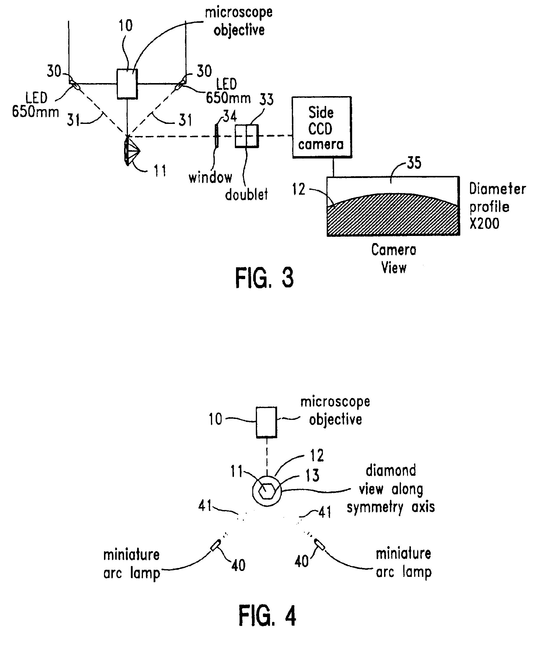
[0126]It is a still further object of the invention to provide a laser energy microinscribing system, comprising a semiconductor excited Q-switched solid state laser energy source; a cut gemstone mounting system, having an aperture; an optical system for focusing laser energy from the laser energy source, through said aperture onto a cut gemstone; a displaceable stage for moving said gemstone mounting system with respect to said optical system so that said focused laser energy is presented to desired positions on said gemstone having a control input; an imaging system for viewing the gemstone from one or more vantage points; and a rigid frame supporting said laser, said optical system and said stage in fixed relation, to resist differential movements of said laser, said optical system and said stage and increase immunity to vibrational misalignments.

Problems solved by technology

The accuracy of known embodiments of this system are limited by vibration and laser steering system accuracy.
Thus, repositioning to form complete characters or graphics is unnecessary.

Method used


Image

  • System and method for gemstone microinscription
  • System and method for gemstone microinscription
  • System and method for gemstone microinscription

Examples


Embodiment Construction

[0155]The detailed preferred embodiments of the invention will now be described with respect to the drawings. Like features of the drawings are indicated with the same reference numerals.

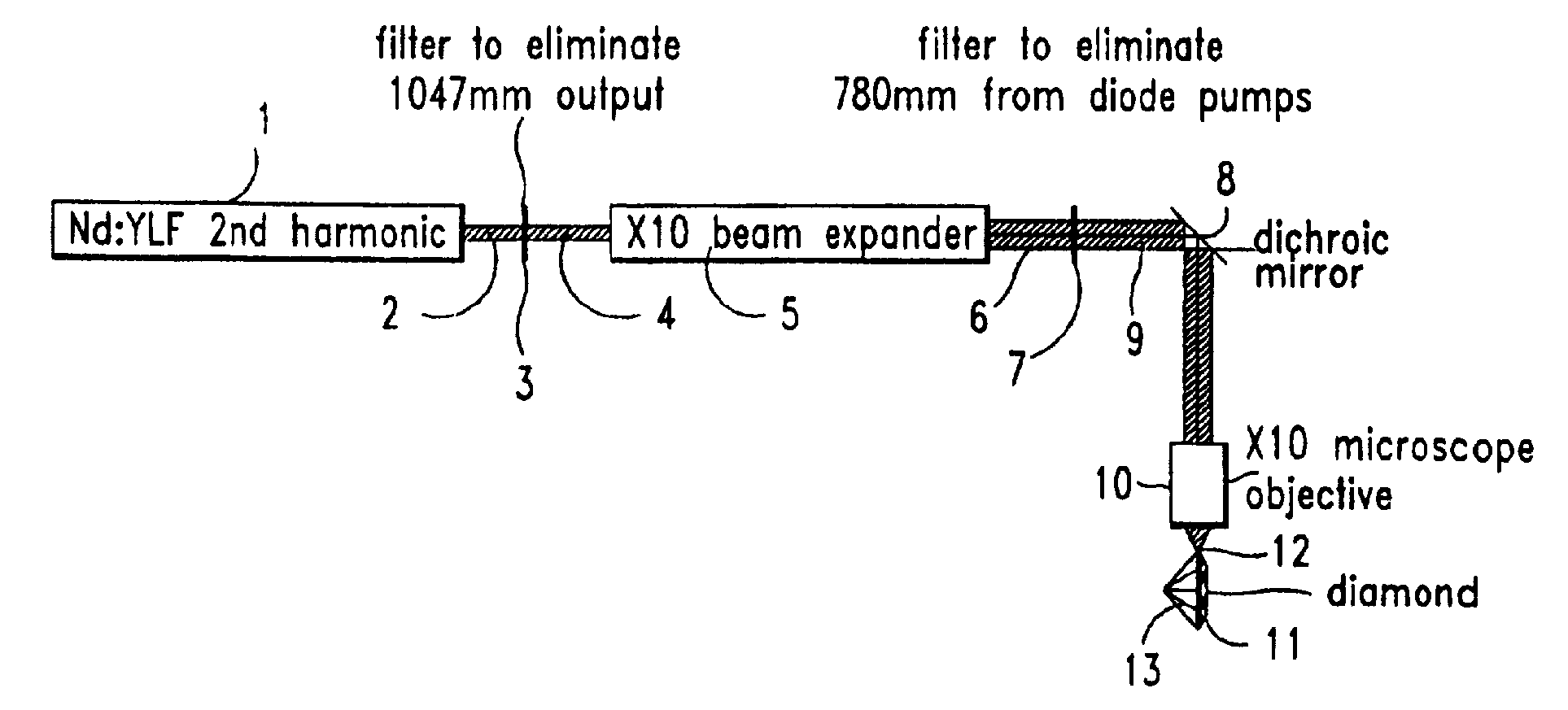
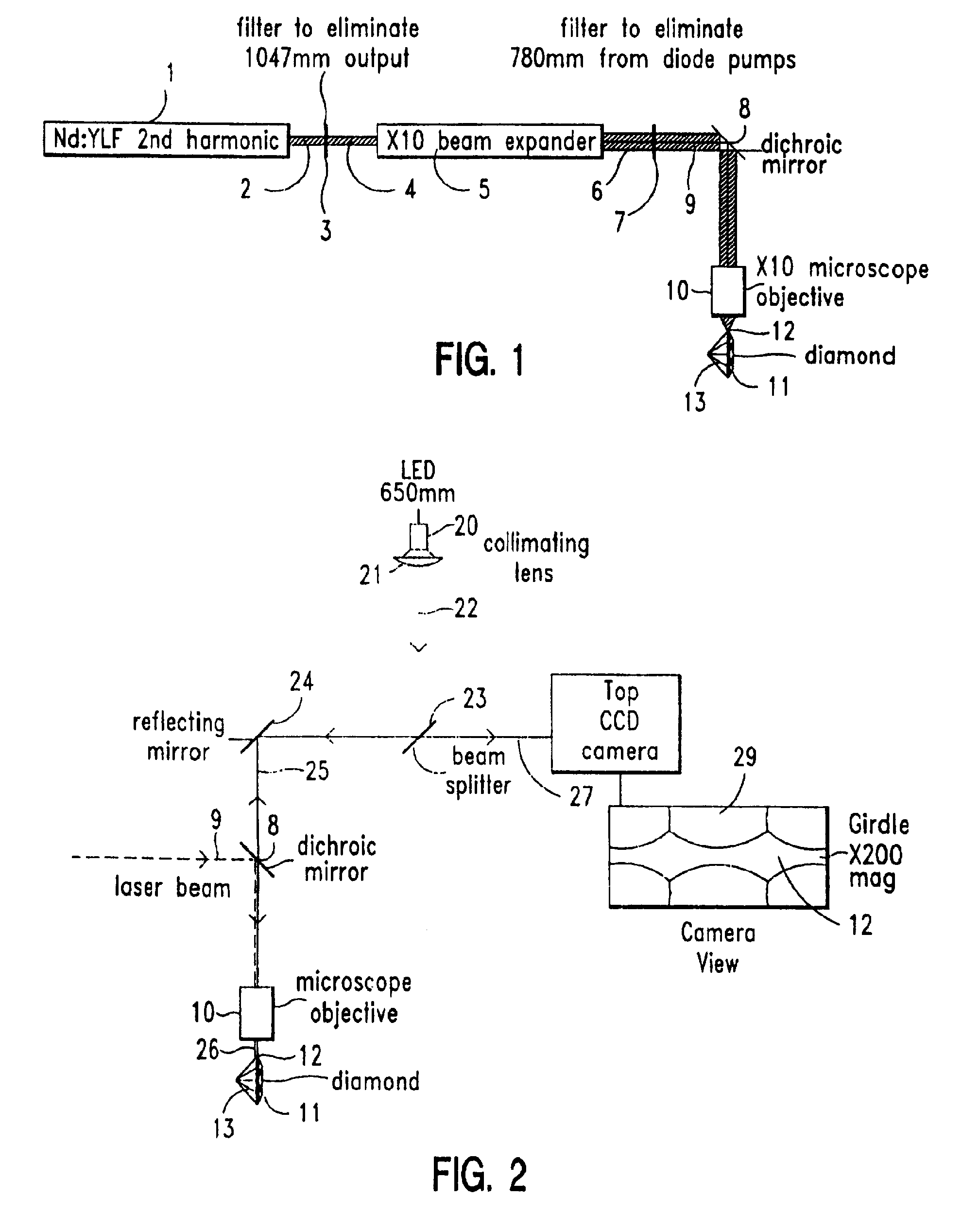
[0156]The system according to the present invention may be used to micro-inscribe alpha / numeric characters on the girdle of diamonds 13. The gemstone may also be another type of gemstone, for example, colored precious or semiprecious gemstones. It is based on a pulse laser 1, and preferably a Q-switched laser diode pumped solid state laser, to provide minimum volume and installation requirements, and optimum compatibility with any office environment.

[0157]A preferred laser based inscribing system according to the present invention thus contains the following primary elements:

[0158]In a vibration isolated frame 140 with shock absorbers 141, at the positions of support:

[0159](1) Laser diode pumped laser 1 and programmable power supply 14, with a Beam Expander 5. (2) Optical assembly containing guiding...


PUM

PropertyMeasurementUnit
weightaaaaaaaaaa
pixel sizeaaaaaaaaaa

Abstract

A gemstone micro-inscription system, comprising an energy source, a spatial light modulator, and a control, the control controlling a spatial light pattern modulation of the spatial light modulator, wherein the spatial light modulator exposes a photoresist on the gemstone, which selectively impedes an etching process to produce a pattern on the gemstone corresponding to the spatial light modulation pattern.

Description

FIELD OF THE INVENTION[0001]The present invention relates to the field of systems and methods for inscribing indicia on a surface of gemstones.BACKGROUND OF THE INVENTION[0002]A known system, as described in U.S. Pat. No. 4,392,476, incorporated herein by reference, for inscribing diamonds includes a Nd:YAG (1.06 μm, frequency doubled) Q-switched laser which marks diamonds by graphitizing the surface at a laser focal point. The beam position is computer controlled to create overlapping treated regions. The accuracy of known embodiments of this system are limited by vibration and laser steering system accuracy.[0003]U.S. Pat. No. 4,467,172, incorporated herein by reference, describes a laser beam diamond inscribing system, which provides a Q-switched flashlamp pumped YAG laser (1.06 μm, frequency doubled) with the diamond mounted on a computer-controlled positioning table for inscribing alphanumeric characters. See also, U.S. Pat. Nos. 2,351,932, 3,407,364, 3,597,198, 3,622,739, 3,77...

Claims


Application Information

Patent Timeline
Patent Type & Authority Applications(United States)
IPC IPC(8): B23K26/38B23K15/08
CPCB23K15/08B23K26/0003C04B41/009C04B41/0045C04B41/0036B23K26/0861B23K26/0665B23K26/032B23K26/04B23K26/0639B23K26/0648C04B41/00C04B14/00B23K26/064B23K26/351
Inventor ROSARIO, CHARLESMORYTO, WILLIAM H.
Owner LAZARE KAPLAN INT
Learn More