

Motor control apparatus and on-vehicle motor drive system
a technology of motor control apparatus and motor drive system, which is applied in the direction of engine-driven generator propulsion, emergency protective circuit arrangement, transportation and packaging, etc., can solve the problems of power change involving a time constant of several tens to hundreds of milliseconds, fluctuation of dc voltage, and inability to change while a vehicle is moving, so as to facilitate the protection from overvoltage
- Summary
- Abstract
- Description
- Claims
- Application Information
AI Technical Summary
Benefits of technology
Problems solved by technology
Method used
Image

Examples
first embodiment
[0037] First of all, the configuration and operation of a motor control apparatus according to the present invention will be described with reference to FIGS. 1 to 4.
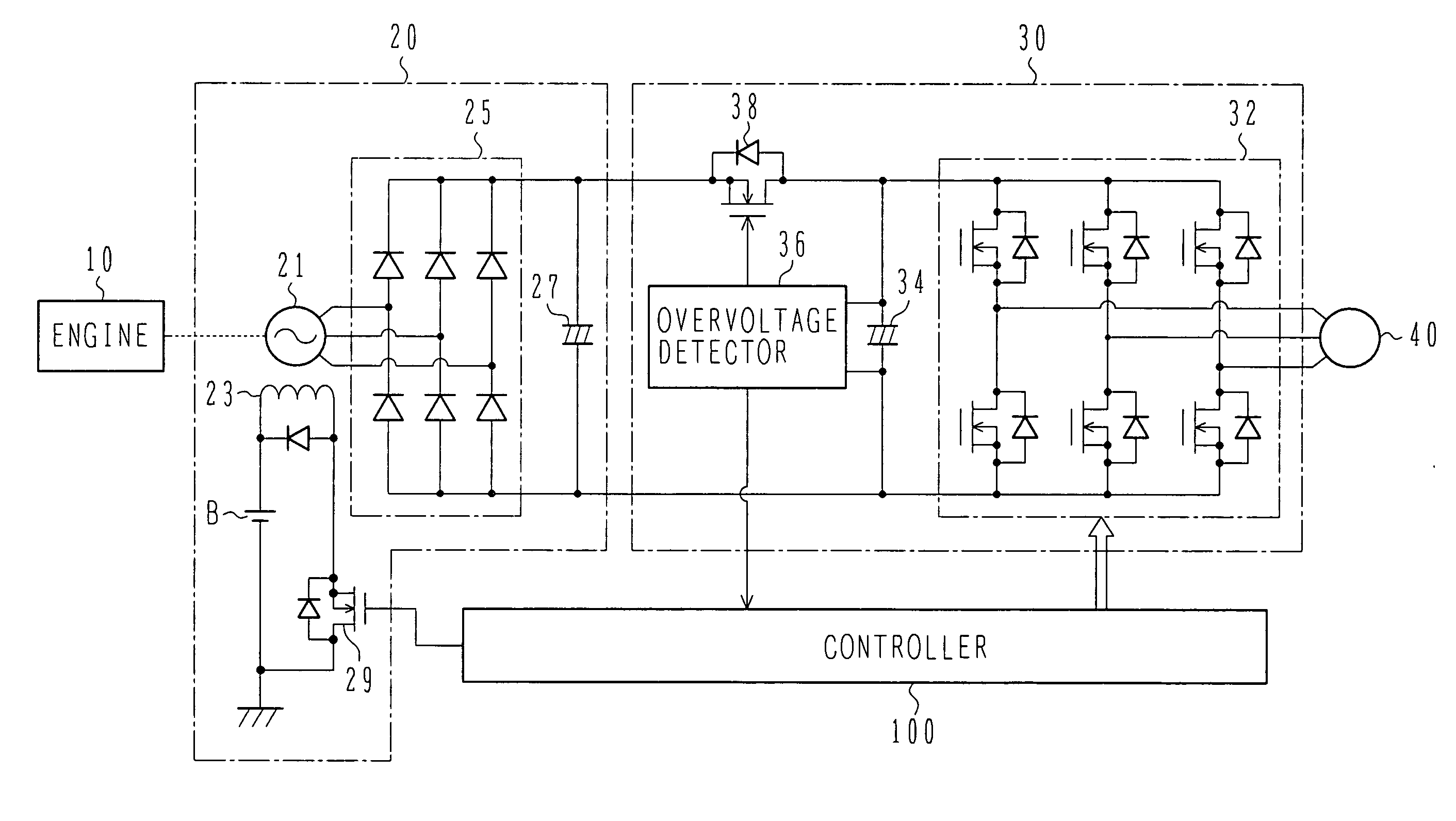
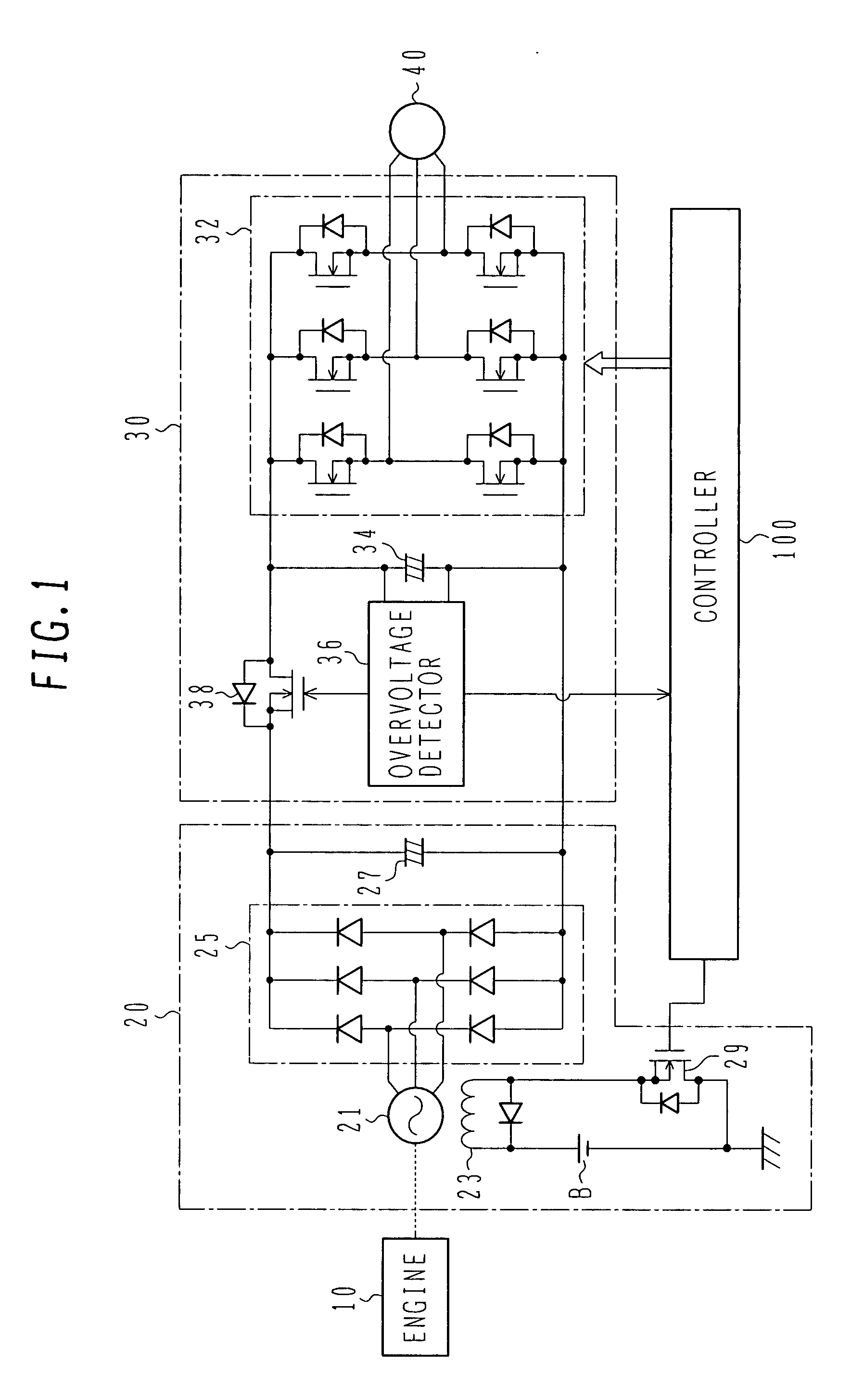
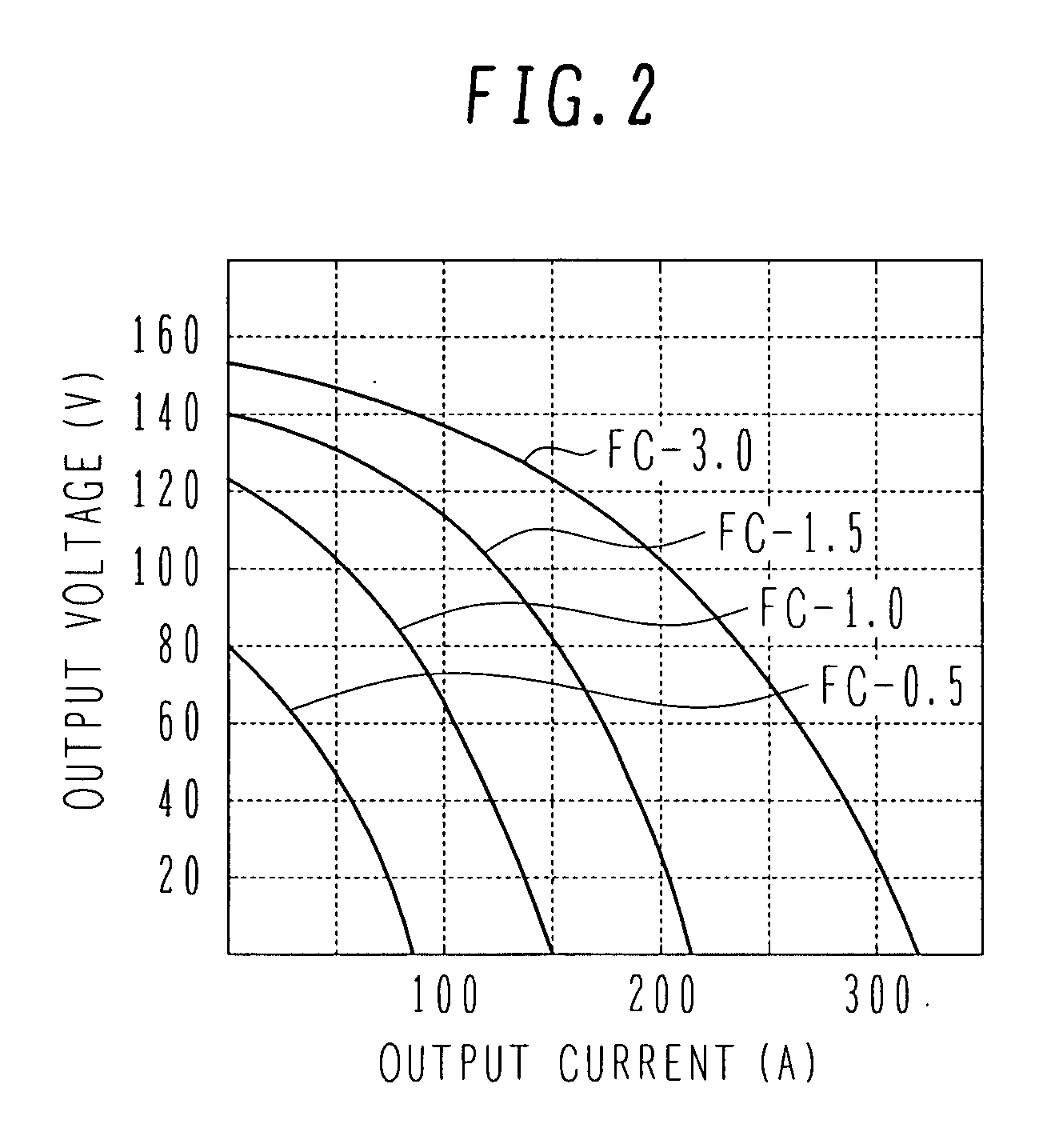
[0038]FIG. 1 is a block diagram showing the configuration of a generator-motor system using a motor control apparatus according to a first embodiment of the present invention. FIG. 2 is a graph showing output voltage vs. output current characteristics of a generator controlled by a motor control apparatus according to the first embodiment of the present invention. FIG. 3 is a graph showing transitions of the output voltage and output current of a generator when an inverter is stopped. The horizontal axes of FIGS. 2 and 3 indicate the output current and the vertical axes indicate the output voltage. FIG. 4 is a graph showing the voltage of a smoothing capacitor when controlled by a motor control apparatus according to the first embodiment of the present invention.
[0039] A generator-motor system shown in FIG. 1 comprises...
second embodiment
[0060] The configuration and operation of a motor control apparatus according to the present invention will be described with reference to FIG. 5.
[0061]FIG. 5 is a block diagram showing the configuration of a generator-motor system using a motor control apparatus according to a second embodiment of the present invention. In FIG. 5, the same numerals indicate the same sections as those of FIG. 1.
[0062] In accordance with the present embodiment, the inverter unit 30A includes a semiconductor switch 38A and a fuse 39 instead of the semiconductor switch 38 of FIG. 1. The Semiconductor switch 38A is located between the power supply line connecting the inverter 32 with the power generation unit 20 and the ground line. For the semiconductor switch 38A, a high-voltage type thyristor which can withstand higher voltage and higher current than the semiconductor switch 38 of FIG. 1 is used. The fuse 39 is located on the power supply line connecting the inverter 32 with the power generation uni...
third embodiment
[0069] The configuration and operation of a motor control apparatus according to the present invention will be described with reference to FIG. 6.
[0070]FIG. 6 is a block diagram showing the configuration of a generator-motor system using a motor control apparatus according to a third embodiment of the present invention. In FIG. 6, the same numerals indicate the same sections as those of FIG. 1.
[0071] In accordance with the present embodiment, a rectifier 25B of the power generation unit 20B uses series circuits of thyristors TH1, TH2, and TH3 and diodes instead of the series circuits of two diodes. The overvoltage detector 36B outputs control signals which stop the gates of the thyristors TH1, TH2, and TH3 if the end-to-end voltage of the smoothing capacitor 34 becomes higher than the reference voltage.
[0072] With this configuration, if the overvoltage detector 36A detects voltage rise of the smoothing capacitor 34, the gates of the thyristors TH1, TH2, and TH3 are stopped to inte...
PUM
 Abstract
Description
Claims
Application Information