Hook shaped ultrasonic cutting blade

a cutting blade and ultrasonic technology, applied in the field of ultrasonic cutting blades, can solve the problems of difficult to initiate and direct a cut, the ability to create a curved or compound angle cut is extremely limited, and the significant thickness of viable bone is lost in the cutting procedure, etc., to achieve the effect of improving the cutting speed, small width and difficult to guid

Active Publication Date: 2008-01-10
MISONIX INC
View PDF39 Cites 209 Cited by
  • Summary
  • Abstract
  • Description
  • Claims
  • Application Information

AI Technical Summary

Benefits of technology

[0030]The cutting edges of a blade in accordance with the present invention are generally continuous, i.e., have no teeth, serrations or voids. This continuity provides a smooth contact surface essential when making precise cuts. In contrast, in an ultrasonic cutting blade having teeth, serrations or interruptions, the feel of the instrument changes and the instrument is more difficult to guide as the teeth, serrations, or interruptions are moved across the bone at the surgical site. Teeth on the blade edge not only do not improve the cutting speed but make it difficult to keep the edge on a predetermined cut line. The continuous blade edges of the present invention also give the cutting process a consistent feel to the surgeon, similar to the fe

Problems solved by technology

While traditional saws are functional, they have many disadvantages.
With either the band or reciprocating saws, for instance, it is not easy to initiate and direct a cut.
With all blades the ability to create a curved or compound angle cut is extremely limited by the blade chosen.
The relatively thick blades have a wide kerf; so that a significant thickness of the viable bone is lost in the cutting procedure.
Above all, the relatively slow linear or tangential speeds of conventional bone saw blades coupled with the teeth necessary for cutting result in high frictional losses, which becomes manifested as heat.
Cutting the jaw between the teeth will cause loss of teeth if the bone is damaged or does not heal quickly.
In these cases, the costs and patient discomfort increases dramatically.
Of course, this technique increases operative time and clinician fatigue.
While these devices are superior to the traditional saws in several aspects such as reduced kerf size, reduced noise, and superior ability for making complex geometric cuts, the temperature rise in bone due to frictional heating at the blade/tissue interface is still a significant problem.
The problem is exacerbated with the use of ultrasonics due to the rapid motion involved as compared to

Method used


Image

  • Hook shaped ultrasonic cutting blade
  • Hook shaped ultrasonic cutting blade

Examples


Embodiment Construction

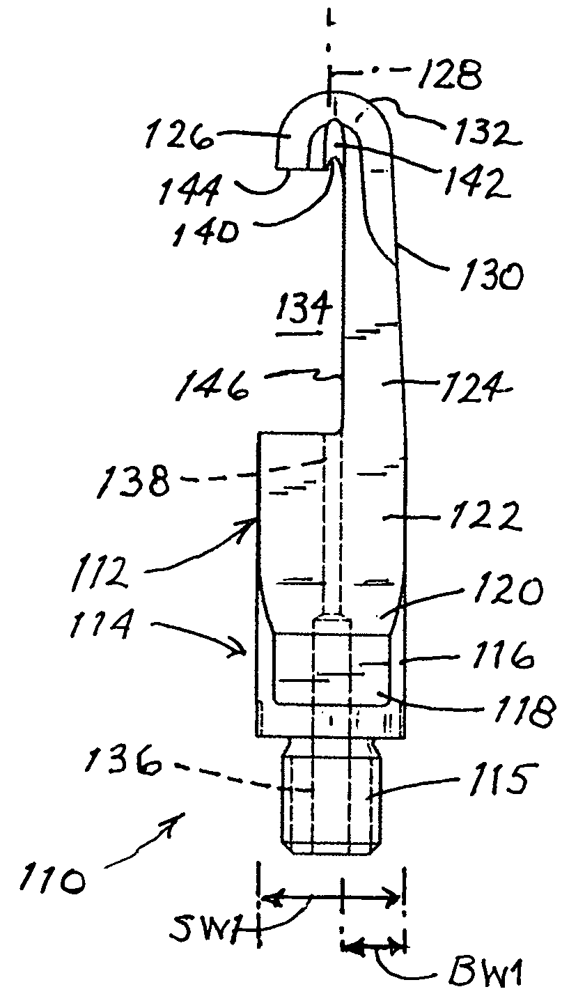
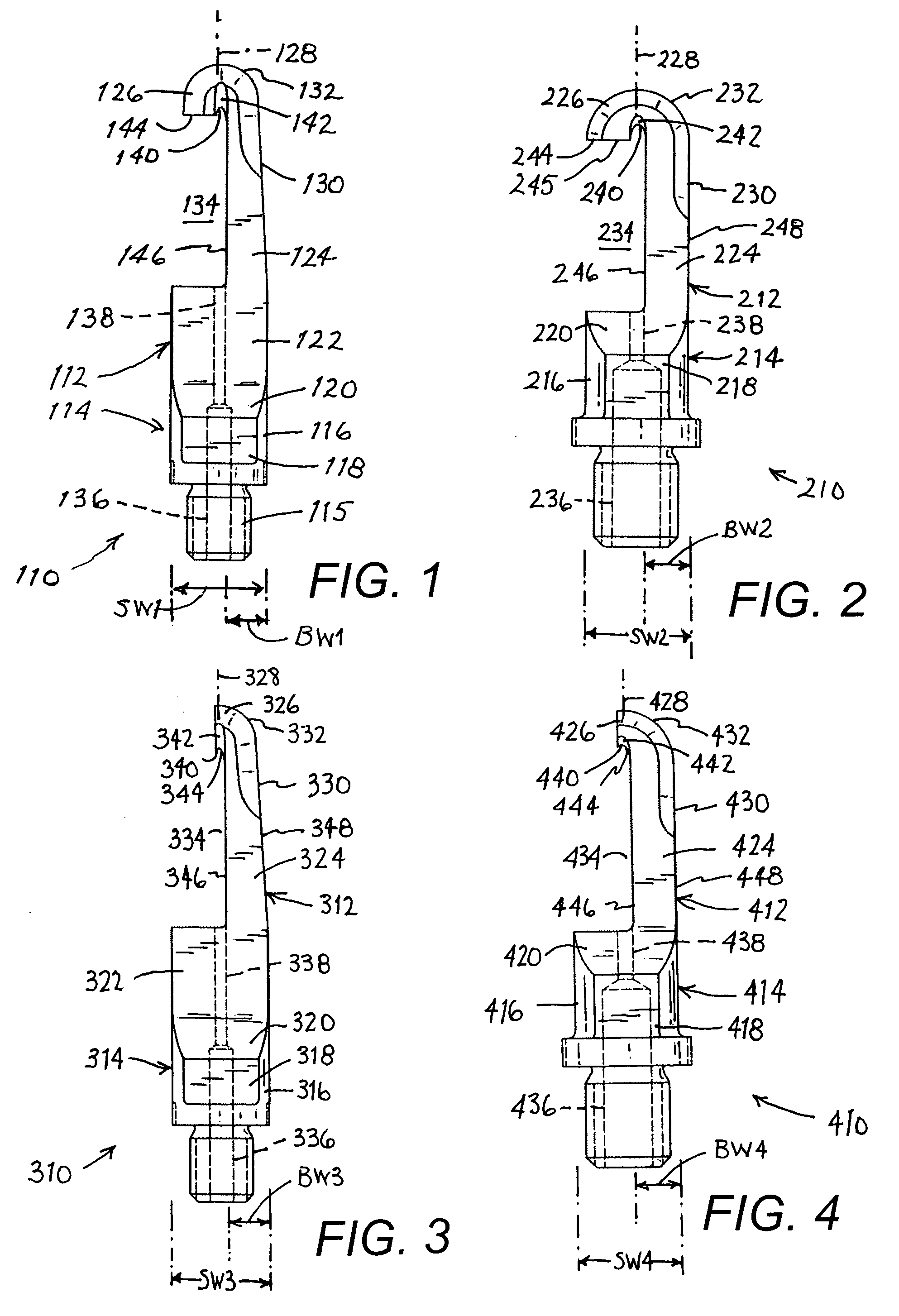
[0042]As depicted in FIG. 1, an ultrasonic surgical blade 110 comprises a blade body 112 and a shank 114. Shank 114 is fixed at one end to blade body 112 and is provided at an opposite end with an externally threaded neck 115 for connecting blade 110 to a source of ultrasonic vibrations (not shown). Shank 114 includes a cylindrical body 116 provided on opposing sides with a pair of planar surfaces 118 engageable by a wrench for alternatively tightening and loosening the blade from the source of ultrasonic vibrations. Shank 118 is formed at a distal end with a pair of inclined surfaces 120 that smoothly connect to blade body 112.

[0043]Blade body 112 includes a proximal plate shaped portion 122, an elongate longitudinal portion 124, and a hook-shaped distal end portion 126 all integrally continuously formed with each other. Blade body 112 is eccentrically disposed relative to a longitudinal axis 128 of blade 110 and particularly of shank 114. Elongate blade portion 124 is slightly tap...


PUM


Abstract

An ultrasonic surgical blade has a blade body and a shank. The shank is fixed at one end to the blade body and is operatively connectable at an opposite end to a source of ultrasonic vibrations. The shank has a longitudinal axis. The blade body is eccentrically disposed relative to the axis.

Description

FIELD OF THE INVENTION[0001]This invention relates to an ultrasonic cutting blade. The blade is particularly useful in a surgical application to cut tissue such as cartilage and bone.BACKGROUND OF THE INVENTION[0002]In the field of orthopedics, the cutting of living bone is a prerequisite for many procedures. Such procedures include the reconstruction of damaged tissue structures due to accidents, the grafting of healthy bone into areas damaged by disease, or the correction of congenital facial abnormalities like a receding chin line. Over several centuries, these tasks were performed through the utilization of devices called bone saws.[0003]Traditional bone saws are categorized into several basic categories. Hand powered saws or drills are just that, hand held devices which require the operator to move the device in a fashion similar to that used for carpentry tools. Powered devices, whether electric or pneumatic, are of either the reciprocating or rotary type. The reciprocating de...

Claims


Application Information

Patent Timeline
IPC IPC(8): A61B18/04
CPCA61B17/320068A61B2017/320072A61B17/148A61B2017/320076A61B17/142A61B2017/320078A61B2017/320075
Inventor PARASCHIV, MIRCEANOVAK, THEODORE A.D.DARIAN, ALEXANDER L.MANNA, RONALD R.
Owner MISONIX INC
Why Eureka
Try Eureka