Carbon dioxide capture systems and methods

a carbon dioxide and carbon dioxide technology, applied in the field of carbon dioxide capture, can solve the problems of not being cost-effective when considered, the cost of cosub>2 /sub>capture using current technology, can be as high as $150 per ton, and is generally estimated to represent three-fourths of the total cos

Inactive Publication Date: 2008-01-17
GENERAL ELECTRIC CO
View PDF10 Cites 24 Cited by
  • Summary
  • Abstract
  • Description
  • Claims
  • Application Information

AI Technical Summary

Problems solved by technology

Existing CO2 capture technologies, however, are not cost-effective when considered in the context of sequestering CO2 from power plants.
The cost of CO2 capture using current technology, however, can be as high as $150 per ton—much too high for carbon emissions reduction applications.
Furthermore, carbon dioxide capture is generally estimated to represent three-fourths of the total cost of a carbon capture, storage, transport, and sequestration system.

Method used


Image

  • Carbon dioxide capture systems and methods
  • Carbon dioxide capture systems and methods
  • Carbon dioxide capture systems and methods

Examples


Embodiment Construction

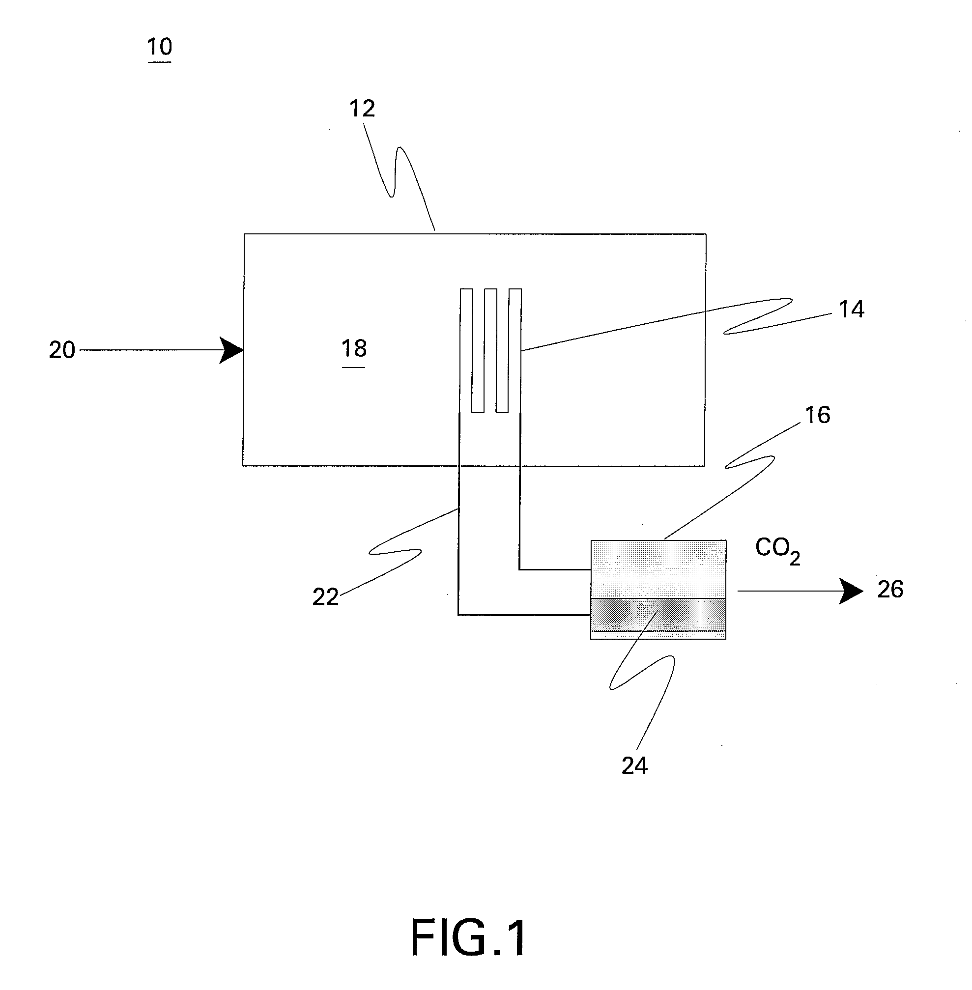
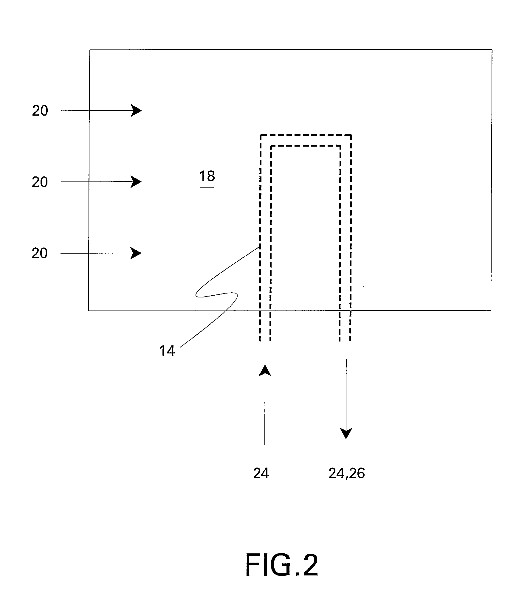
[0012]A carbon dioxide separation system 10 comprises a heat exchanger 12, a separator 14 and a condenser 16, as shown in FIG. 1 and FIG. 2. Heat exchanger 12 comprises a first flow path 18 for directing a fluid comprising carbon dioxide 20 therethrough and a second flow path 22, defined at least in part by separator 14, for directing a heat transfer fluid 24 therethrough. In one embodiment, separator 14 comprises a material or structure that enables selective permeability of carbon dioxide. Any suitable material may be used for the separator 14 provided that that material is stable at the operating conditions and has the required permeance and selectivity at those conditions. Materials known to be selective for CO2 include, for example, certain inorganic and polymer materials. Inorganic materials include microporous carbon, microporous silica, microporous titanosilicate, microporous mixed oxide, and zeolite materials.

[0013]While not to be limited by a particular theory, mechanisms ...


PUM

PropertyMeasurementUnit
selective permeabilityaaaaaaaaaa
temperatureaaaaaaaaaa
thermal and mass transferaaaaaaaaaa

Abstract

A carbon dioxide separation system comprises a heat exchanger having a first flow path for directing a fluid comprising carbon dioxide, for example an exhaust gas, therethrough and a second flow path for directing a heat transfer fluid therethrough, a separator comprising a material with selective permeability of carbon dioxide for separating the first and second flow paths and for promoting thermal transfer and carbon dioxide transport therebetween, and a condenser for condensing the heat transfer fluid to isolate the carbon dioxide. In another embodiment, a carbon dioxide separation system comprises an energy production system for generating electricity and an exhaust gas including carbon dioxide at a temperature greater than about 300C, a heat exchanger having a first flow path for directing the exhaust gas therethrough and a second flow path for directing water therethrough to promote thermal transfer between the first flow path and the second flow path and produce a flow of steam within the second flow path, a carbon dioxide extraction circuit in thermal and mass transfer relationship with the exhaust gas comprising a third flow path for directing a heat transfer fluid therethrough, wherein the carbon dioxide extraction circuit comprises a material with selective permeability of carbon dioxide for promoting thermal transfer and carbon dioxide transport between the exhaust gas and the heat transfer fluid to produce a mixed flow of a gaseous heat transfer fluid and carbon dioxide within the third flow path, and a condenser for receiving the mixed flow and for condensing the mixed flow to isolate the carbon dioxide.

Description

BACKGROUND[0001]This invention relates generally to carbon capture and more specifically to methods and systems for capturing carbon dioxide.[0002]Before carbon dioxide (CO2) gas can be sequestered from power plants and other point sources, it must be captured in a relatively pure form. On a mass basis, CO2 is the nineteenth largest commodity chemical in the United States, and CO2 is routinely separated and captured as a byproduct of industrial processes such as synthetic ammonia production, hydrogen (H2) production or limestone calcination.[0003]Existing CO2 capture technologies, however, are not cost-effective when considered in the context of sequestering CO2 from power plants. Most power plants and other large point sources use air-fired combustors, a process that exhausts CO2 diluted with nitrogen. For efficient carbon sequestration, the CO2 in these exhaust gases must be separated and concentrated.[0004]CO2 is currently recovered from combustion exhaust by using, for example, ...

Claims


Application Information

Patent Timeline
Patent Type & Authority Applications(United States)
IPC IPC(8): B01D53/22C01B32/50
CPCB01D53/1475B01D53/229Y02C10/10Y02C10/06B01D2257/504Y02C20/40Y02P20/129
Inventor BOWMAN, MICHAEL JOHNSANBORN, STEPHEN DUANEEVULET, ANDREI TRISTANRUUD, JAMES ANTHONY
Owner GENERAL ELECTRIC CO
Why Eureka
Try Eureka