

Microchannel-Type Evaporator and System Using the Same
a microchannel-type evaporator and evaporator technology, applied in indirect heat exchangers, lighting and heating apparatuses, laminated elements, etc., can solve the problem of reducing the heat exchange capacity of evaporators in a region of high heat flux, and achieve the effect of increasing the heat exchange efficiency of a microchannel-type evaporator and reducing the size of the evaporator
- Summary
- Abstract
- Description
- Claims
- Application Information
AI Technical Summary
Benefits of technology
Problems solved by technology
Method used
Image

Examples
embodiment 1
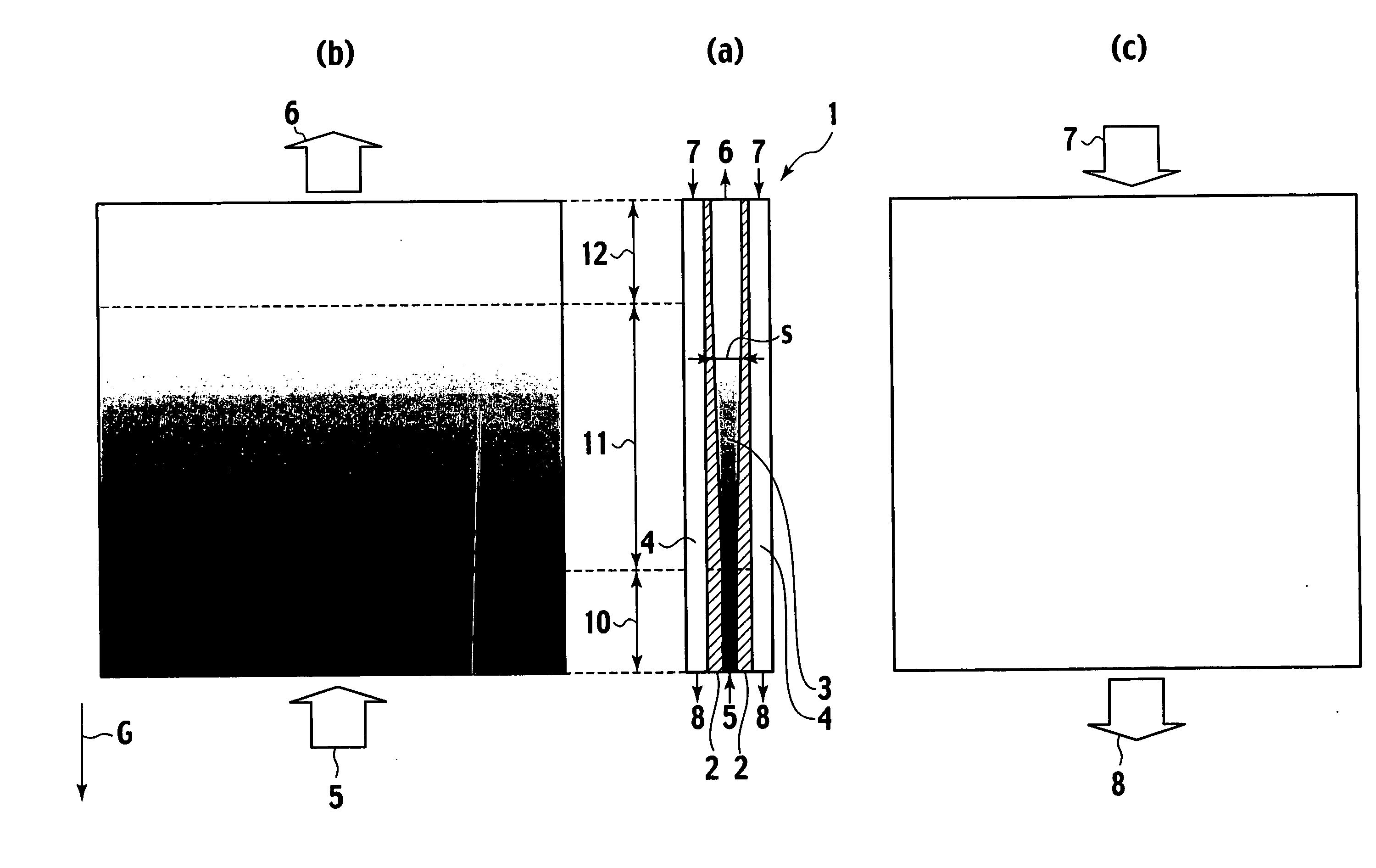
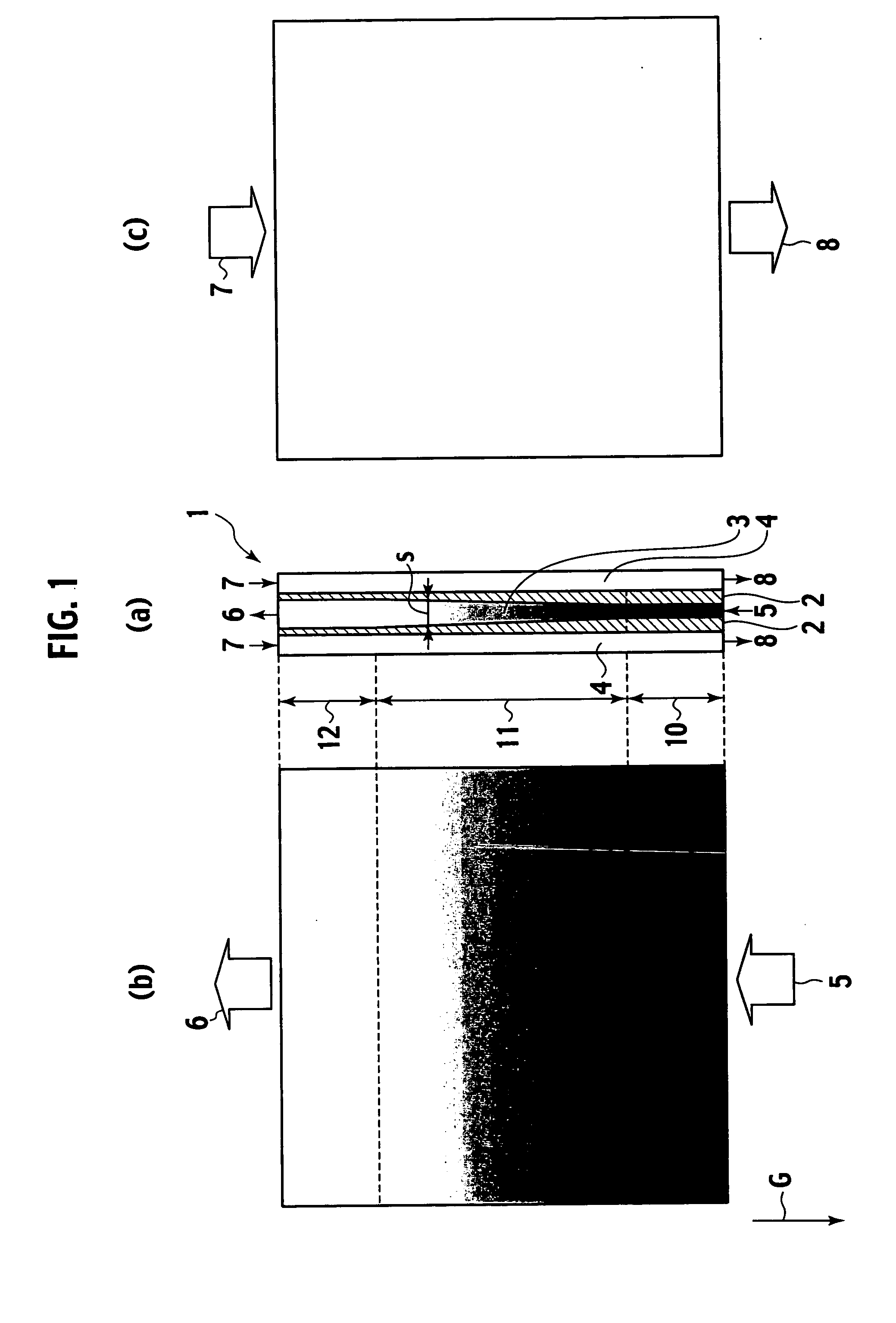
[0045] FIGS. 1(a), 1(b), and 1(c) show a basic constituent unit of Embodiment 1 of the evaporator according to the present invention.
[0046] An evaporator 1 in this embodiment includes two heat transfer plates 2 opposite to each other. Between the heat transfer plates 2, a path 3 through which liquid to be evaporated passes is provided. The path 3 through which liquid to be evaporated passes is placed vertically, that is, along the direction G of gravity force. In the present invention, vertically setting the liquid path means setting the liquid path at such an angle that heat transfer properties in the right and left heat transfer surfaces which form a microchannel do not significantly lose symmetry because of the inclination thereof and, for example, includes setting the same at an angle of ± about 20 degrees from the vertical.
[0047] Furthermore, in the outside of the heat transfer plates 2, paths 4 through which heating gas passes, is provided. To form a real evaporator, it is p...
embodiment 2
[0062] FIGS. 3(a), 3(b), and 3(c) show a basic constituent unit of Embodiment 2 of the evaporator according to the present invention.
[0063] The configuration of the evaporator 1 itself of Embodiment 2 is, similar to the configuration of the evaporator of Embodiment 1, of the countercurrent flow type in which the flow directions of the liquid to be evaporated and the heating gas are opposite to each other. This embodiment is an embodiment in the case where the mass flow rate of the heating gas is not negligible compared to that of the liquid to be evaporated and the temperature of the heating gas decreases from the gas inlets 7 to the gas outlets 8.
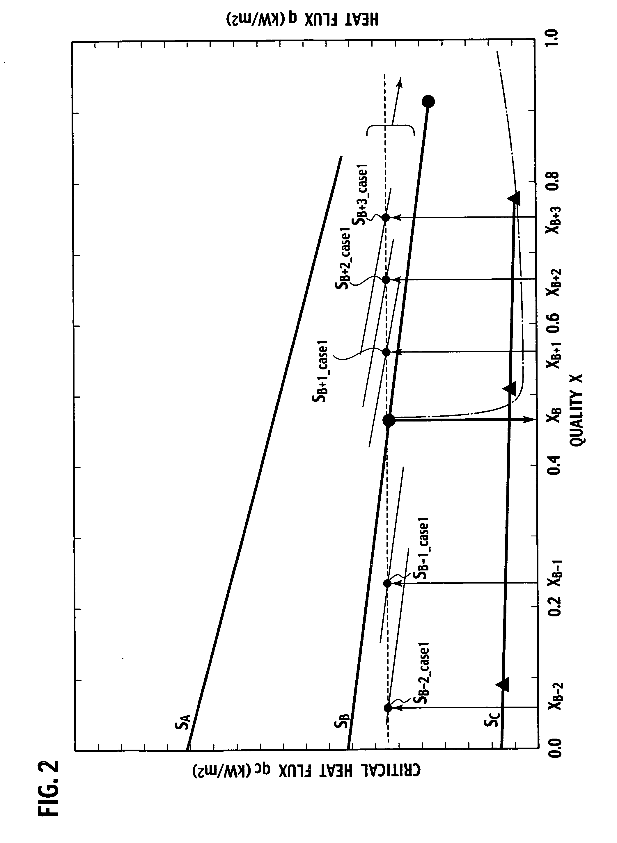
[0064]FIG. 4 shows a change (a dashed line) in heat flux from the heating gas to the liquid to be evaporated and critical heat flux of each path space in this embodiment. As indicated by the dashed line of FIG. 4, the heat flux is low where the quality is small, and the heat flux is high where the quality is large. This is because the fo...
embodiment 3
[0069] FIGS. 5(a), 5(b), and 5(c) show a basic constituent unit of Embodiment 3 of the evaporator according to the present invention.
[0070] As shown in FIG. 5(a), an evaporator 1 in this embodiment is an embodiment in which space between two opposite heat transfer plates 2 serves as a liquid path 3. Sections outside of the heat transfer plates 2 serve as gas paths 4. To form a real evaporator, it is preferable that the evaporator has a structure in which a plurality of the basic constituent units shown in the drawing are arranged in parallel.
[0071] At the lower end of the liquid path 3, a liquid inlet 5, through which the liquid to be evaporated is supplied to the evaporator 1, is provided. At the upper end of the liquid path, a vapor outlet 6 is provided. The liquid to be evaporated evaporates as flowing from the bottom to the top of the evaporator 1. On the other hand, the heating gas is supplied from gas inlets 7, which are provided at the lower end of the evaporator, and disch...
PUM
 Abstract
Description
Claims
Application Information