
Coil switching of an electric generator

Inactive Publication Date: 2008-01-17
OCEAN POWER TECHNOLOGIES
View PDF9 Cites 70 Cited by
  • Summary
  • Abstract
  • Description
  • Claims
  • Application Information

AI Technical Summary

Benefits of technology

[0009]Applicants' invention resides, in part, in the recognition of the problems discussed above, and, in part, in the use of an electric generator with multiple winding (coil) sections and switching means to selectively interconnect selected coil sections in different configurations to maximize the efficiency of the power conversion system over a wide range of operating conditions.
[0014]When used in combination with a WEC, the components of the PTO are typically sized to handle the high forces and velocities (and power) that can occur in heavy sea conditions. These forces and velocities can be an order of magnitude (or more) above those experienced in normal or low sea conditions. Similarly, the components of the PCS are sized to handle the high currents and voltages (and power) that result during heavy sea conditions. In normal and low sea conditions, the generator typically rotates more slowly than its rated speed. The resultant output voltage is proportionally lower. This lower voltage does not adversely affect the electrical efficiency of the generator. However, as discussed above, it can adversely affect the efficiency of the power conversion system because of fixed voltage drops in the power conversion solid-state switches. For example, a transistor's forward conduction drop (of approximately 2 volt) is insignificant when the generator voltage is 200V. But, it becomes more and more significant as the generator voltage decreases below 20 volts. Given that two or more solid-state switches may be conducting (on) at a time, the effect of switch conduction losses is amplified.
[0015]In a system embodying the invention, selected sections of the coils may be configured and / or reconfigured to selectively cause the output voltage of the electric generator to tend to be high relative to the fixed voltage drops due to the switches in the power converter. In heavy sea conditions (high amplitude waves) tending to produce a large generator output voltage, selected sections of the generator windings may be connected in parallel in order to keep the generator output voltage within limits and to increase the current handling capability of the generator. In low sea conditions (lower amplitude waves), when the generator is rotating slowly, tending to produce a lower generator output voltage, selected sections of the generator windings may be connected in series in order to raise the generator output voltage above the fixed voltage drops of the power converter switches.
[0019]In addition to the improvement in generator output power conversion efficiency, the invention can also improve the efficiency of the driving power source due to improved or optimized impedance matching. For example, if the coils are configured in such a way that little voltage is generated, the WEC will have to operate with more motion than is optimum in order to extract power. Similarly, if the windings are configured to generate high voltage with little WEC motion, then less than optimum power is extracted from the waves. The efficiency of the generator system can thus be improved by use of the proper selection of generator coil arrangement.

Problems solved by technology

Although it is known to employ WECs to generate electric power, numerous problems exist in the design of systems for efficiently harnessing the energy contained in ocean waves because the oceans waves vary very widely in frequency and amplitude over time.
A drawback with this approach is that the same equipment is oversized and inefficient when operated in low sea-state and normal conditions.
If Eg is greater, the efficiency loss due to the fixed drops decreases.
However, when Eg is less than 20 volts the efficiency loss increases, above 10%.
For example, If Eg were 10 volts the 2 diode drops result in an efficiency loss of 20%.
Thus for low values of Eg, the losses in the power conversion stage are very significant.

Method used


Image

  • Coil switching of an electric generator
  • Coil switching of an electric generator
  • Coil switching of an electric generator

Examples


Embodiment Construction

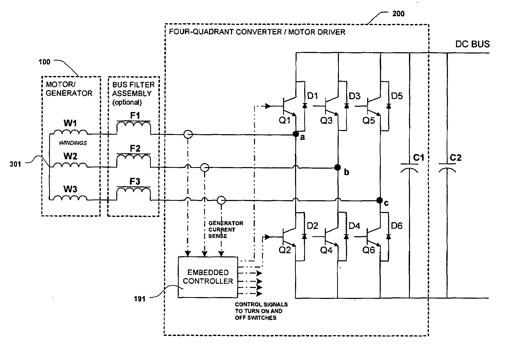
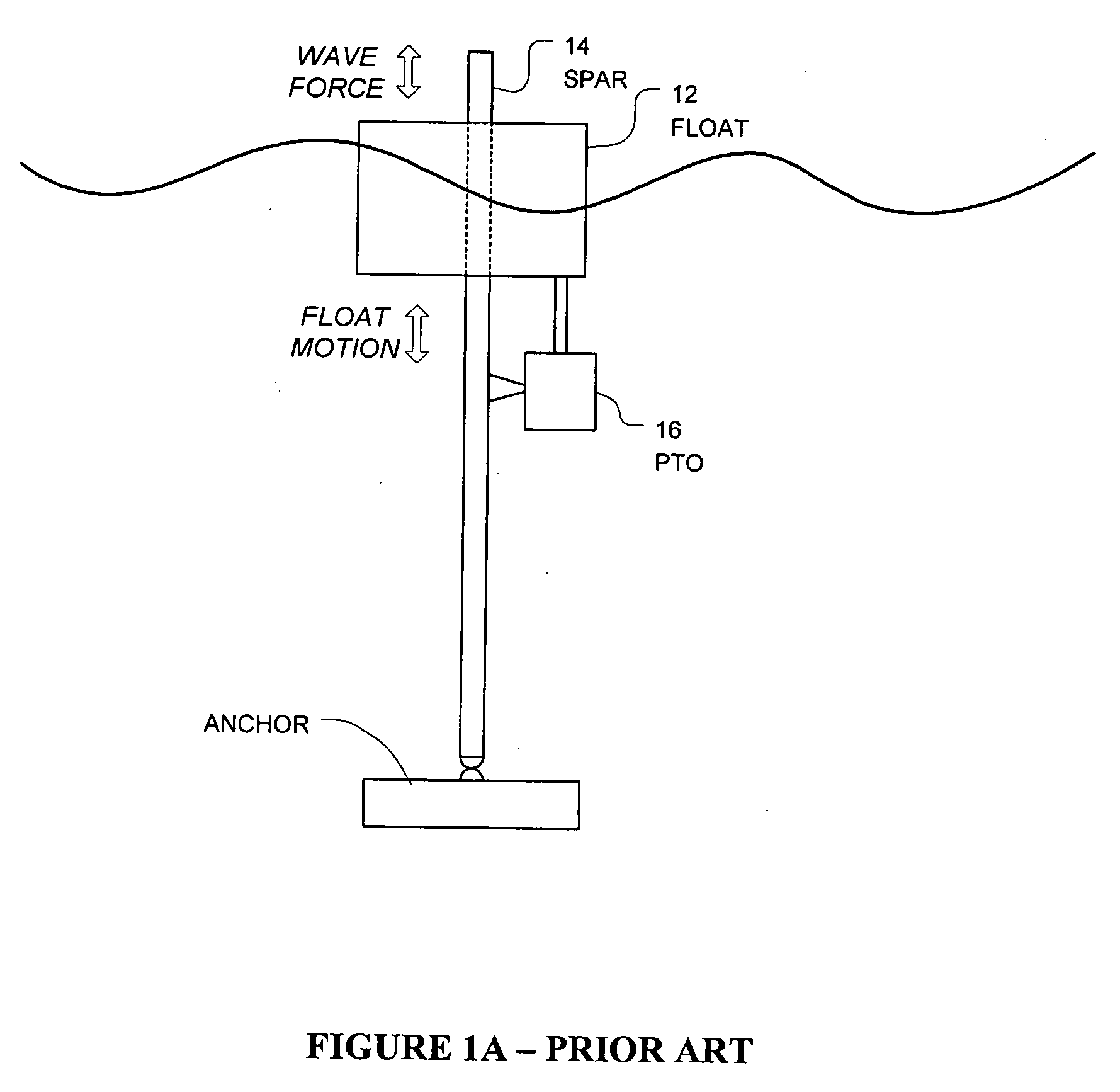
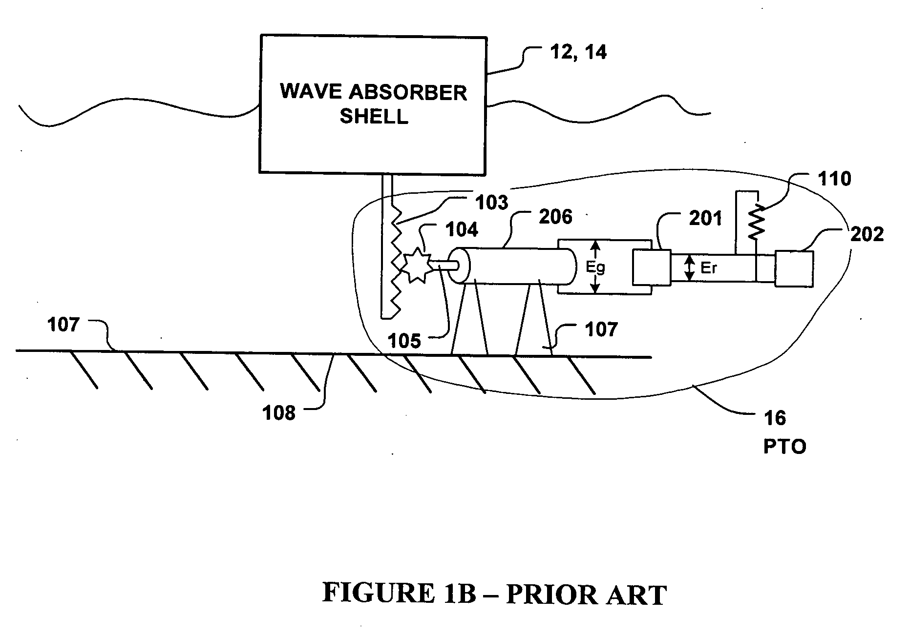
[0037]FIGS. 1A and 1B show generalized versions of an ocean wave energy converter (WEC). A float (or shell), 12, moves up and down relative to a spar, 14, that is anchored to the sea floor. Alternatively, the spar is not anchored and may be allowed to move so as to move out of phase relative to the float. A power-take-off device (PTO), 16, coupled between the float and the spar converts the mechanical power available from the WEC into electrical power. In FIG. 1B, the PTO device includes a linear-to-rotary translator (e.g. rack and pinion gear assembly, ball screw assembly, hydraulic cylinder and motor assembly, or pneumatic cylinder and motor assembly) coupled to a rotary electric generator. In this system the generator's rotational velocity is proportional to the relative velocity between the float and spar. The output voltage, Eg, of the generator is in turn approximately proportional to the rotational velocity of the generator shaft as illustrated in FIG. 2.

[0038]As shown in FIG...


PUM


Abstract

An electric generator includes multiple coil sections and switches connected to the multiple coil sections for selectively interconnecting the coil sections in series, or in parallel, or in a series-parallel configuration across first and second power terminals for producing a controlled AC voltage across these power terminals. The electric generator, with its multiple coils and interconnecting switches permitting reconfiguration of the coils, enables systems subjected to widely varying conditions and forces, such as a wave energy converter (WEC), to be operated with increased efficiency. The generator may also include multiple windings which can be selectively interconnected into a wye or a delta configuration to also control the output voltage produced by the generator and increase the efficiency of the power conversion system, particularly at low values of voltage.

Description

BACKGROUND OF THE INVENTION[0001]This invention relates to switching the coils (windings) of an electric generator to alter the configuration of the coils of the generator in order to improve the efficiency of the generator and a system employing the generator.[0002]The invention is of particular interest in applications where an electric generator is subjected to a wide range of operating conditions and forces such as, for example, those encountered with wave energy converters (WECs), wind turbines and, in general, any system which may be subjected to widely varying forces.[0003]By way of example, a WEC, responsive to the motion of the waves in a body of water, may include an electric generator which is used to produce electricity in response to the motions of the waves, which can vary, in frequency and amplitude, over a very large range. Various wave energy converter (WEC) systems are known. For example, reference is made to U.S. Pat. No. 6,291,904 which issued Sep. 18, 2001, titl...

Claims


Application Information

Patent Timeline
IPC IPC(8): H02P9/00
CPCH02P9/48H02P2101/15H02P2101/10
Inventor STEWART, DAVID B.LISKA, TIMOTHY J.
Owner OCEAN POWER TECHNOLOGIES
Features
  • Generate Ideas
  • Intellectual Property
  • Life Sciences
  • Materials
  • Tech Scout
  • Unparalleled Data Quality
  • Higher Quality Content
  • 60% Fewer Hallucinations
Learn More