Non-linear image mapping using a plurality of non-coplanar clipping planes

a clipping plane and non-linear image technology, applied in the field of display systems, can solve the problems of counter to the desires of most users, the resolution of available display technologies exceeds that of typical image generation and distribution infrastructure, etc., and achieves the effects of low latency, high quality, and high usable resolution

Active Publication Date: 2008-01-17
ESTERLINE BELGIUM BVBA
View PDF11 Cites 16 Cited by
  • Summary
  • Abstract
  • Description
  • Claims
  • Application Information

AI Technical Summary

Benefits of technology

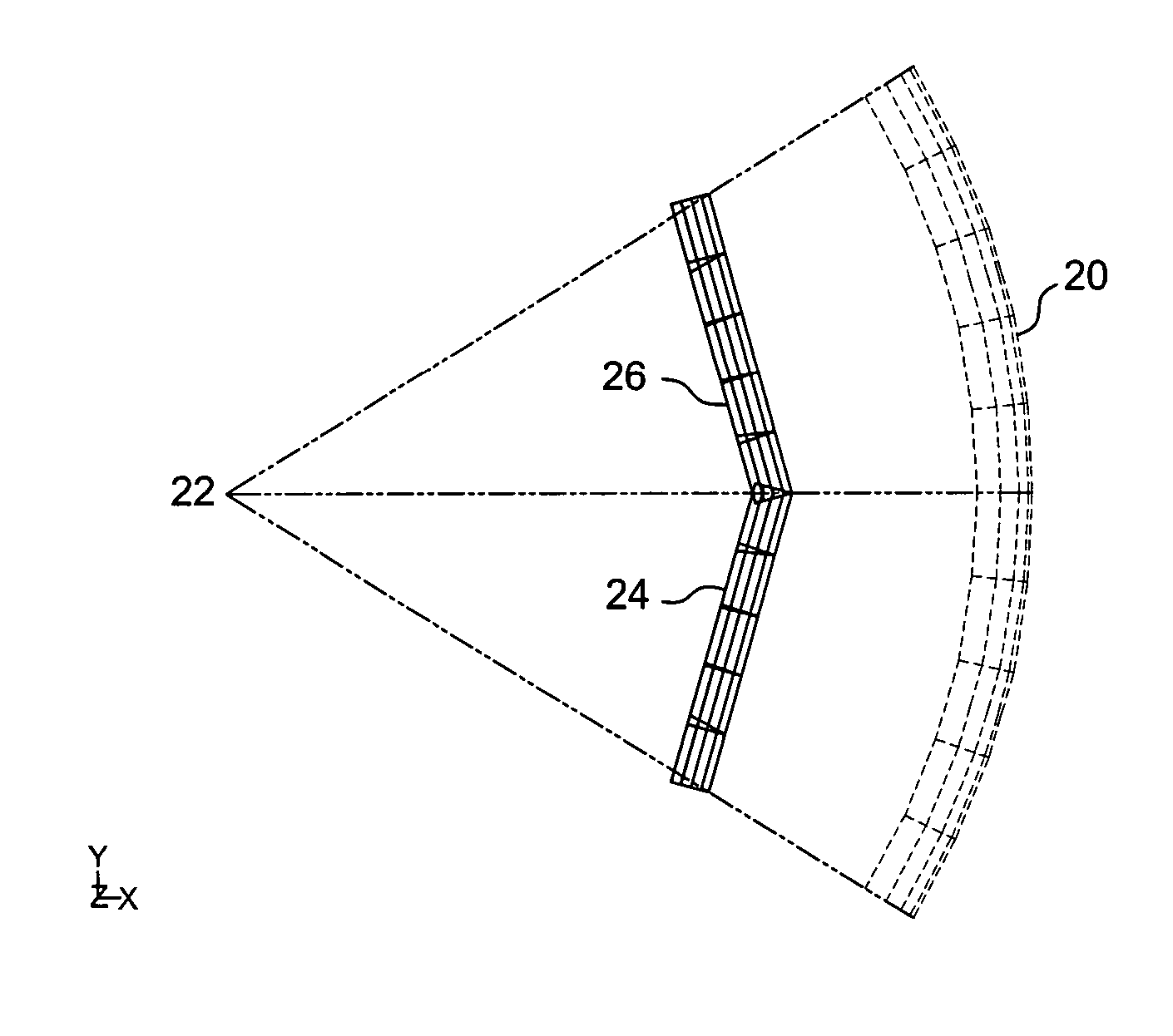
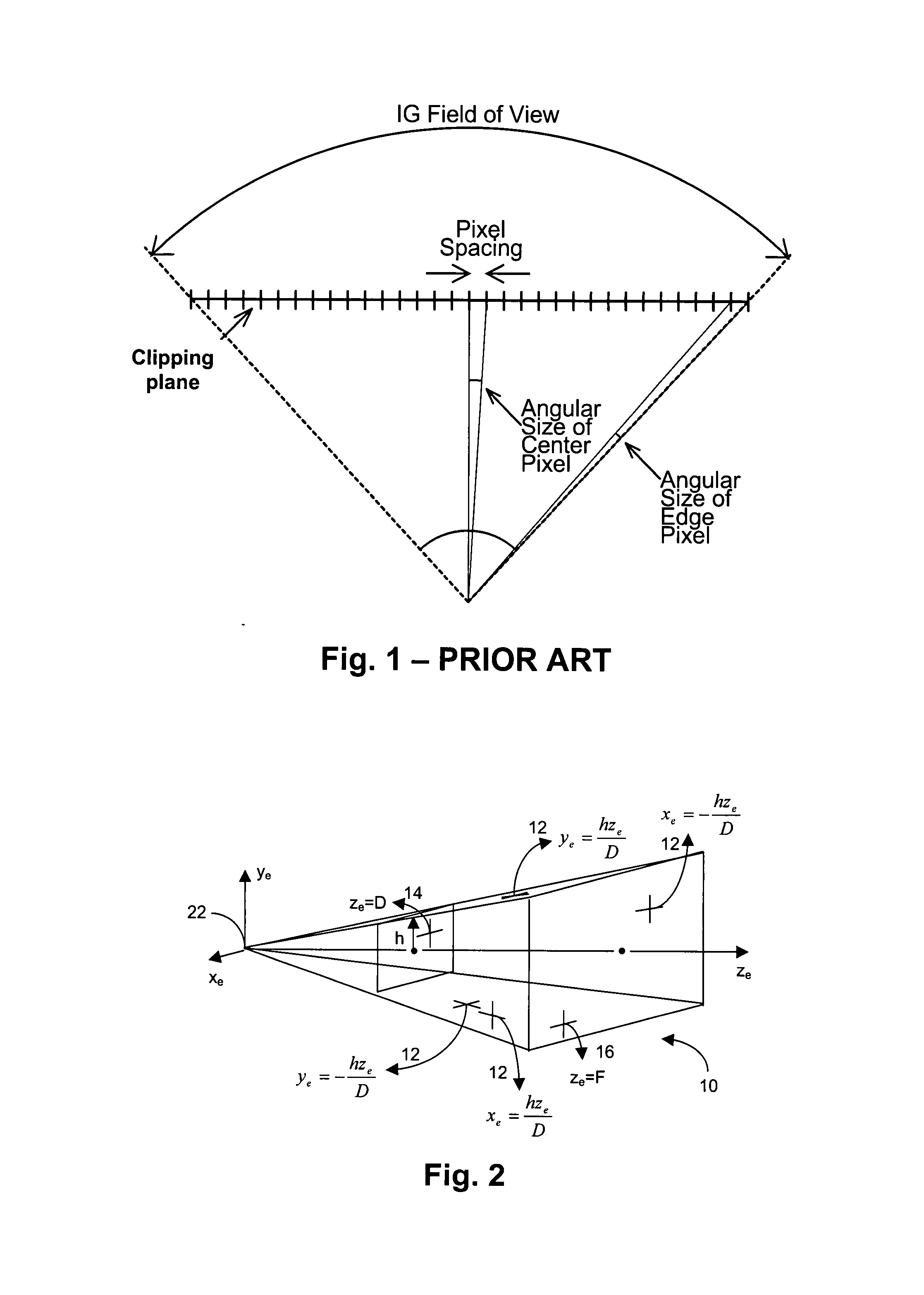
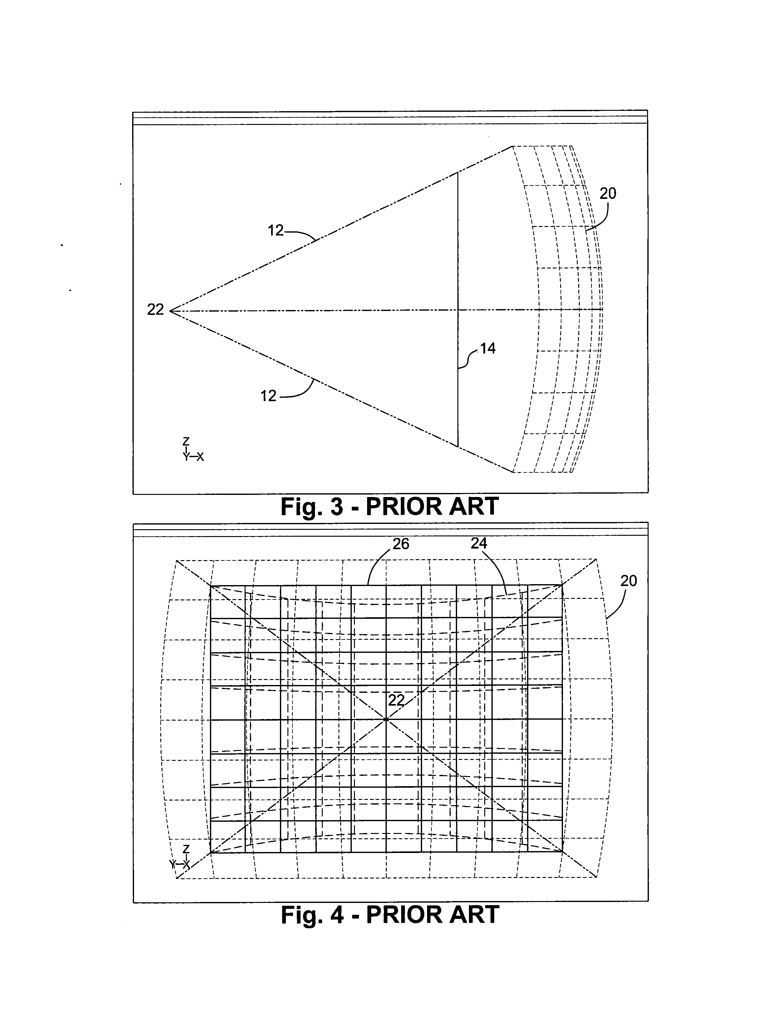
[0015] According to embodiments of the present invention, the display processing system may furthermore comprise means for providing a plurality of component images, to be received by the input channels of the display processing system. The means for providing a plurality of component images may be at least one image generator (IG). In case of just one IG being present, this IG would form a number of images, e.g. render a number of images each with its own non-coplanar clipping plane to be combined in the combiner. The images could be sequentially generated or they could be tiled in the IGs output. Alternatively, the means for providing a plurality of component images may be a plurality of IGs each providing one or more component images. Alternatively, the means for providing a plurality of component images may be an array of video cameras. In this case the frustum and clipping planes are defined by the imager and optics of the cameras. The means for providing a plurality of component images may be adapted to provide component images in the form of column subsections of the image to be displayed. Synchronisation means for synchronising the provision of the component images may advantageously be provided for reasons of low latency and/or high quality imagery with no tearing at the overlaps between component images emanating from different sources.
[0016] A display processing system in accordance with embodiments of the present invention may furthermore comprise an imaging means for receiving the combined image data and producing an image. This way, a display system may be formed. The display system may be for projection

Problems solved by technology

A challenge to industry exists in the current market as the resolution of available display technologies exceeds that of typical image generation and distribu

Method used


Image

  • Non-linear image mapping using a plurality of non-coplanar clipping planes
  • Non-linear image mapping using a plurality of non-coplanar clipping planes
  • Non-linear image mapping using a plurality of non-coplanar clipping planes

Examples


Embodiment Construction

[0050] The present invention will be described with respect to particular embodiments and with reference to certain drawings but the invention is not limited thereto but only by the claims. The drawings described are only schematic and are non-limiting. In the drawings, the size of some of the elements may be exaggerated and not drawn on scale for illustrative purposes. The dimensions and the relative dimensions do not correspond to actual reductions to practice of the invention.

[0051] Furthermore, the terms first, second, third and the like in the description and in the claims, are used for distinguishing between similar elements and not necessarily for describing a sequential or chronological order. It is to be understood that the terms so used are interchangeable under appropriate circumstances and that the embodiments of the invention described herein are capable of operation in other sequences than described or illustrated herein.

[0052] Moreover, the terms top, bottom, over, ...


PUM


Abstract

A display processing system for providing video signals for displaying an image is provided. The display processing system comprises input channels for receiving a plurality of component images, each component image being a portion of the complete image for display, the image data of each component image being defined by a view frustum having a clipping plane, and a combiner for combining the image data of the component images. According to the present invention, at least two clipping planes of two of the view frustums are non-coplanar. Such display processing system corrects for the defect of driving angular resolution to the edges of the field of view of a display system, in particular for large field-of-view display systems, and balances the overall system angular resolution by allowing each image generator channel to render to an optimal view frustum for its portion of the complete image.

Description

CROSS-REFERENCE TO RELATED APPLICATIONS [0001] The benefit of U.S. Provisional Application No. 60 / 830,336 filed Jul. 13, 2006 is claimed under 35 U.S.C. §119(e) and the entirety of said application is incorporated herein by reference.TECHNICAL FIELD OF THE INVENTION [0002] The present invention relates to display systems (comprising display means for displaying images) or display processing systems (comprising means for generating video outputs, but no display means for displaying those video outputs), for example projection systems for projection of images on a screen. The present invention may be particularly useful for high resolution large field-of-view display systems that may be used, for example, in entertainment, flight, vehicle, marine or leisure simulators, or in presentation applications. BACKGROUND OF THE INVENTION [0003] A challenge to industry exists in the current market as the resolution of available display technologies exceeds that of typical image generation and d...

Claims


Application Information

Patent Timeline
IPC IPC(8): G09G5/00
CPCH04N9/3147H04N9/12
Inventor CLODFELTER, ROBERT MARK
Owner ESTERLINE BELGIUM BVBA
Why Eureka
Try Eureka