
Header for Supplying Gas in Fuel Cell and Fuel Cell Power System

a fuel cell and power system technology, applied in the direction of fuel cells, solid electrolyte fuel cells, reactant parameter control, etc., can solve the problems of increasing equipment cost, reducing total efficiency, and reducing the space factor, so as to eliminate the generation of the temperature variation between the cells

Inactive Publication Date: 2008-01-17
HITACHI LTD
View PDF3 Cites 0 Cited by
  • Summary
  • Abstract
  • Description
  • Claims
  • Application Information

AI Technical Summary

Benefits of technology

[0006]It is possible to efficiently heat an area having a lowered temperature to eliminate a generation of a temperature gradient by placing a surface combustion burner within a power-generating reaction chamber and contriving a burner-placing location. However, this method requires the surface combustion burner and a mechanism for controlling the burner. For this reason, an increase of accessory equipments is inevitable, which causes a reduction in total efficiency, an increase in equipment cost, degradation in space factor and the like.
[0007]Accordingly, it is an object of the invention to provide a gas-supplying header for a fuel cell wherein the variation in temperature profile between fuel cells can be eliminated without accessory equipments such as a surface combustion burner. It is another object of the present invention to provide a fuel cell power system including such a gas-supplying header.
[0013]According to present invention, the gas having the high temperature can be supplied to the lower temperature area of the fuel cell body, by utilizing a combustion heat of an unreacted gas which is not utilized for a power-generating reaction in the fuel cell, without need for accessory equipments such as a surface combustion burner and a mechanism for controlling the accessory equipments. In this manner, the generation of the variation in temperature between the cells can be eliminated.

Problems solved by technology

However, this method requires the surface combustion burner and a mechanism for controlling the burner.
For this reason, an increase of accessory equipments is inevitable, which causes a reduction in total efficiency, an increase in equipment cost, degradation in space factor and the like.

Method used


Image

  • Header for Supplying Gas in Fuel Cell and Fuel Cell Power System
  • Header for Supplying Gas in Fuel Cell and Fuel Cell Power System
  • Header for Supplying Gas in Fuel Cell and Fuel Cell Power System

Examples


Embodiment Construction

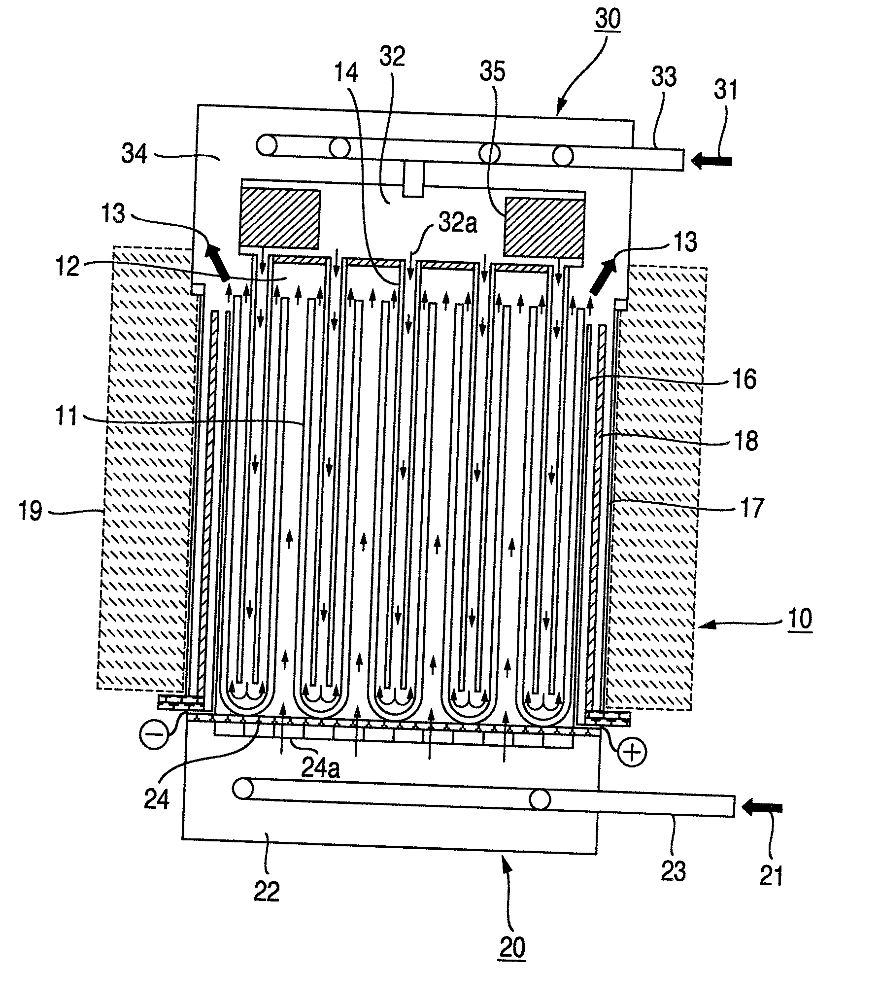
[0019]FIG. 1 is a schematic view showing the arrangement of a fuel cell power system according to an embodiment of the present invention. The illustration of the detailed structure of a fuel cell is omitted in FIG. 1, but the fuel cell is of a three-layer structure comprising a fuel electrode (anode), an electrolyte and an oxidizer electrode (cathode). Two types of fuel cells are known, in one of which the inside of an end-closed cylindrical cell tube is a fuel electrode and the outside of the tube is an oxidizer electrode, and in the other of which the inside is an oxidizer electrode and the outside is a fuel electrode. The present invention can be applied to both of these types. FIG. 1 shows the type of fuel cell in which the inside of the cell tube is the oxidizer electrode and the outside is the fuel electrode.

[0020]The fuel cell power system shown in FIG. 1 is comprised of a fuel cell body 10, a fuel gas-supplying header 20, and an oxidizer gas-supplying header 30. A fuel gas 2...


PUM

PropertyMeasurementUnit
operating temperatureaaaaaaaaaa
temperatureaaaaaaaaaa
temperaturesaaaaaaaaaa

Abstract

The present invention provides a fuel cell power system, in which a combustion exhaust gas having a high temperature and generated by the combustion reaction of unreacted fuel gas and oxidizer gas which are not utilized in a power-generating reaction is introduced into a gas header for distributing the fuel gas or the oxidizer gas to a plurality of fuel cells contained in a fuel cell body, in such a way that a larger amount of heat is transferred to the gas which is to be supplied to the cells disposed in a peripheral area of the fuel cell body by heat exchange, and a smaller amount of the heat is transferred to the gas which is to be supplied to the cells disposed in a central area of the fuel cell body.

Description

BACKGROUND OF THE INVENTION[0001]1. Field of the Invention[0002]The present invention relates to a gas supplying header for supplying a cell reaction gas, such as a fuel gas or an oxidizer gas, to fuel cells, and relates to a fuel cell power system including the gas supplying header. The present invention is particularly applied to an oxidizer gas-supplying header in a fuel cell power system which is operated at a high temperature, such as a solid oxide fuel cell power system.[0003]2. Description of the Related Art[0004]A solid oxide fuel cell power system has been studied and developed extensively, because a power-generating efficiency is high, and a waste heat is utilizable although an operating temperature thereof is as high as about 900° C. in average. Since there is a limit to a power output from single cell in the solid oxide fuel cell power system, a plurality of cells are typically assembled. In order to ensure a high power output, it is necessary to eliminate the variation ...

Claims


Application Information

Patent Timeline
Patent Type & Authority Applications(United States)
IPC IPC(8): H01M8/04
CPCH01M8/04022H01M8/04074Y02E60/50H01M8/243H01M8/04201H01M8/2485H01M8/2457
Inventor YOSHIDA, TADASHITOKOI, HIROMITAKAHASHI, KAZUOTAKAHASHI, SHINNOIE, AKIHIKOGUNJI, AKIRAKOBAYASHI, NARIYOSHI
Owner HITACHI LTD
Features
  • Generate Ideas
  • Intellectual Property
  • Life Sciences
  • Materials
  • Tech Scout
  • Unparalleled Data Quality
  • Higher Quality Content
  • 60% Fewer Hallucinations
Learn More