
Power Output Apparatus and Motor Vehicle

a technology of power output apparatus and motor vehicle, which is applied in the direction of jet propulsion mounting, instruments, analogue processes for specific applications, etc., can solve the problems of troublesome on-off operation of the four clutches, reducing power generation efficiency, and complicated structure of the power output apparatus, so as to simplify the configuration of the motor vehicle and its control procedur

Inactive Publication Date: 2008-01-17
TOYOTA JIDOSHA KK
View PDF1 Cites 27 Cited by
  • Summary
  • Abstract
  • Description
  • Claims
  • Application Information

AI Technical Summary

Benefits of technology

The present invention is directed to a power output apparatus and a motor vehicle that use two internal combustion engines and two motors for efficient power output. The apparatus includes a first connection disconnection structure that connects and disconnects the output shafts of the two engines, and a second connection disconnection structure that connects and disconnects the output shaft of the second engine and the driveshaft. The apparatus also includes a charge state detection unit and a power demand setting module to ensure efficient power output and maintain the state of charge of the accumulator unit. The technical effects of the invention include simplifying the structure of the power output apparatus, enhancing the efficiency of power output, and ensuring efficient output of power.

Problems solved by technology

Such requirement undesirably complicates the structure of the power output apparatus and leads to the troublesome on-off operations of the four clutches.
The selective use of this engine undesirably lowers the power generation efficiency.

Method used


Image

  • Power Output Apparatus and Motor Vehicle
  • Power Output Apparatus and Motor Vehicle
  • Power Output Apparatus and Motor Vehicle

Examples


Embodiment Construction

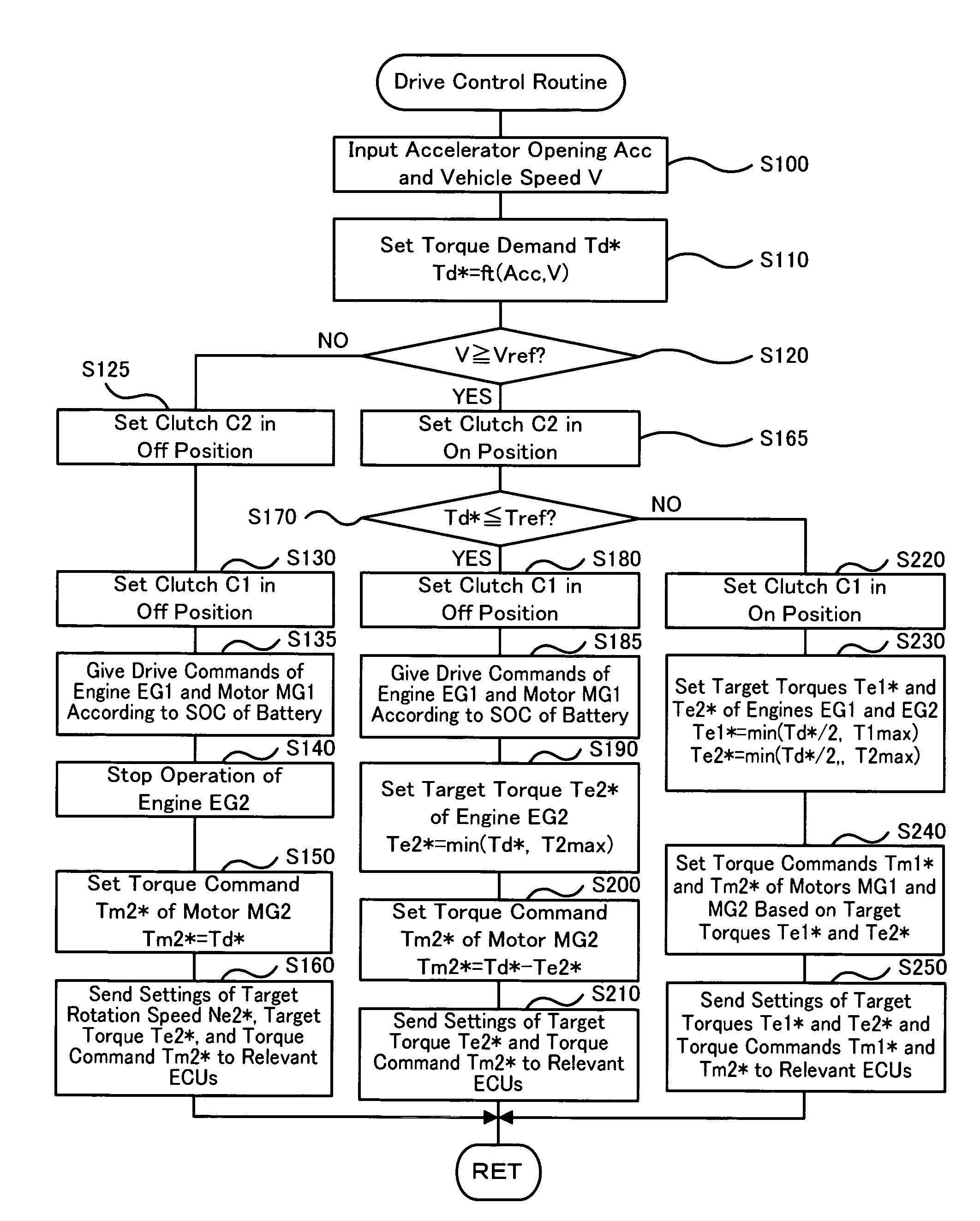
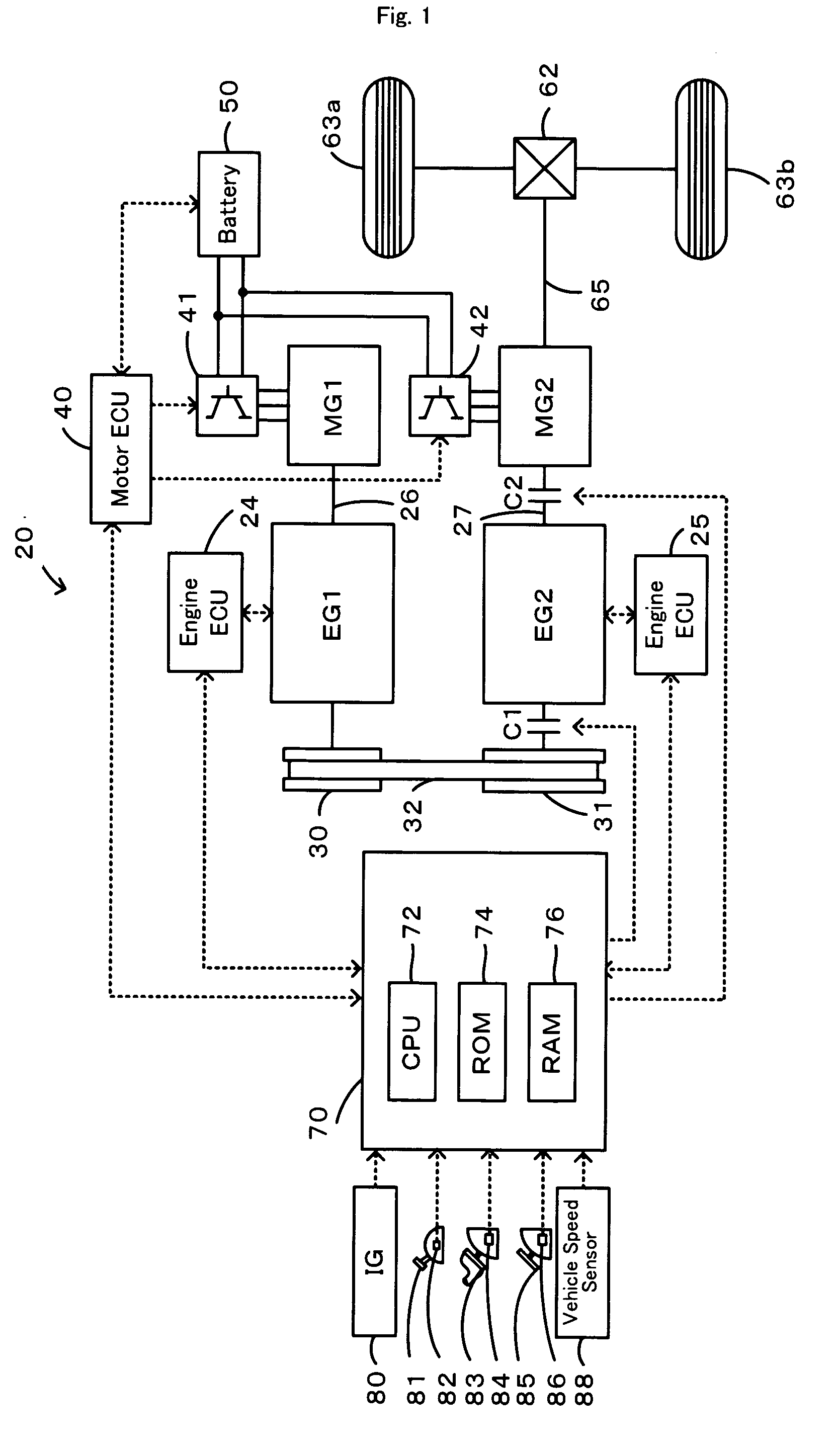
[0032]One mode of carrying out the invention is described below as a preferred embodiment. FIG. 1 schematically illustrates the configuration of a hybrid vehicle 20 equipped with a power output apparatus in one embodiment of the invention. As illustrated, the hybrid vehicle 20 of the embodiment has two engines EG1 and EG2 consuming gasoline to output power, two motors MG1 and MG2 constructed as known synchronous motor generators, and a hybrid electronic control unit 70 controlling the operations of the whole power output apparatus. The engine EG1 has a crankshaft 26 connecting with the motor MG1, which uses the output power of the engine EG1 to generate electric power. The crankshaft 26 of the engine EG1 is linked with a crankshaft 27 of the engine EG2 by means of identical-diameter pulleys 30 and 31, a belt 32, and a clutch C1. The engines EG1 and EG2 are driven at an identical rotation speed in an ON position of the clutch C1. The crankshaft 27 of the engine EG2 is connected via a...


PUM


Abstract

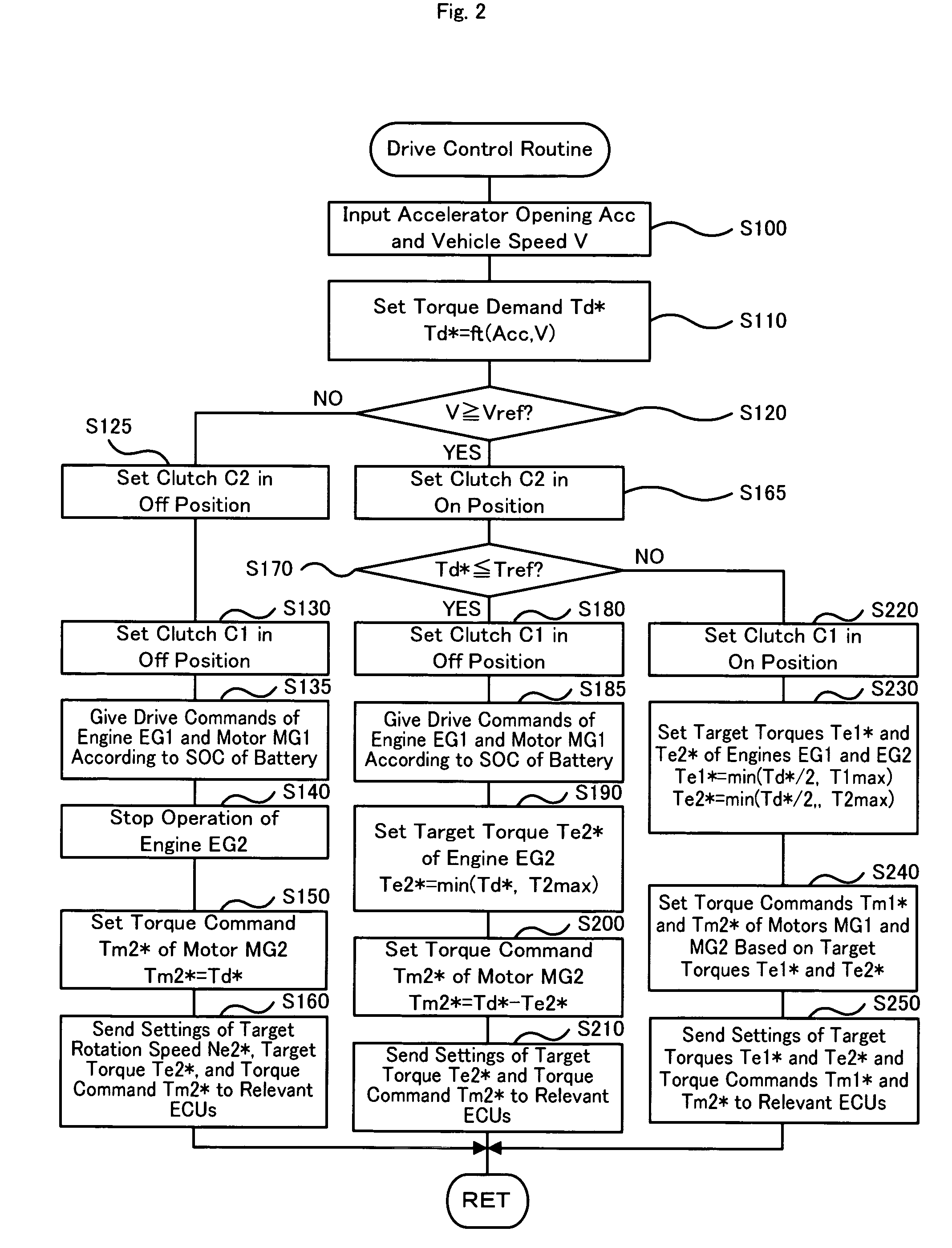
In a power output apparatus of the invention, an engine EG1 is connected with a motor MG1 and is connected with an engine EG2 via a clutch C1. A driveshaft 65 is connected to the engine EG2 via a clutch C2 and is linked with a motor MG2. On a start or in a low speed range, the clutch C2 is set in an OFF position to disconnect the engine EG2 from the driveshaft 65, and the power output apparatus is driven only with the output power of the motor MG2. In an intermediate speed range, the clutch C2 is set in an ON position, and the power output apparatus is driven mainly with the output power of the engine EG2 that is driven with high efficiency. This arrangement enhances the total energy efficiency. The power output apparatus of the invention has a simple structure including the two clutches in addition to the two engines and the two motors.

Description

TECHNICAL FIELD [0001]The present invention relates to a power output apparatus and a motor vehicle.BACKGROUND ART [0002]A proposed power output apparatus has two engines and two motors mounted on a vehicle (see, for example, Japanese Patent Laid-Open Gazette No. H11-311137). The proposed power output apparatus uses a differential gear attached to an input shaft of a transmission, which is linked to drive wheels via another differential gear. The two motors are respectively connected via sets of brakes and clutches to remaining two shafts of the differential gear. Output shafts of the two engines having different output characteristics are respectively connected with rotating shafts of the two motors via clutches. The working engine is changed over between the two engines having the different output characteristics according to the driving conditions of the vehicle.DISCLOSURE OF THE INVENTION[0003]This prior art power output apparatus requires the differential gear, the two brakes, ...

Claims


Application Information

Patent Timeline
Patent Type & Authority Applications(United States)
IPC IPC(8): G06F17/00B60K5/08B60W20/00B60K6/442B60K17/04B60L50/16B60W10/02B60W10/06B60W10/08
CPCB60K5/08B60K6/44B60K6/442B60W10/02B60W10/06Y02T10/6286B60W20/00B60W30/1882B60W2540/10Y02T10/623Y02T10/6234B60W10/08Y02T10/62B60W20/40B60W10/26
Inventor YAMAUCHI, TOMOKAZU
Owner TOYOTA JIDOSHA KK
Learn More