Method And Filter Arrangement For Separating Exhaust Particulates

Inactive Publication Date: 2008-01-24
FLECK CARL MARIA
View PDF14 Cites 31 Cited by
  • Summary
  • Abstract
  • Description
  • Claims
  • Application Information

AI Technical Summary

Benefits of technology

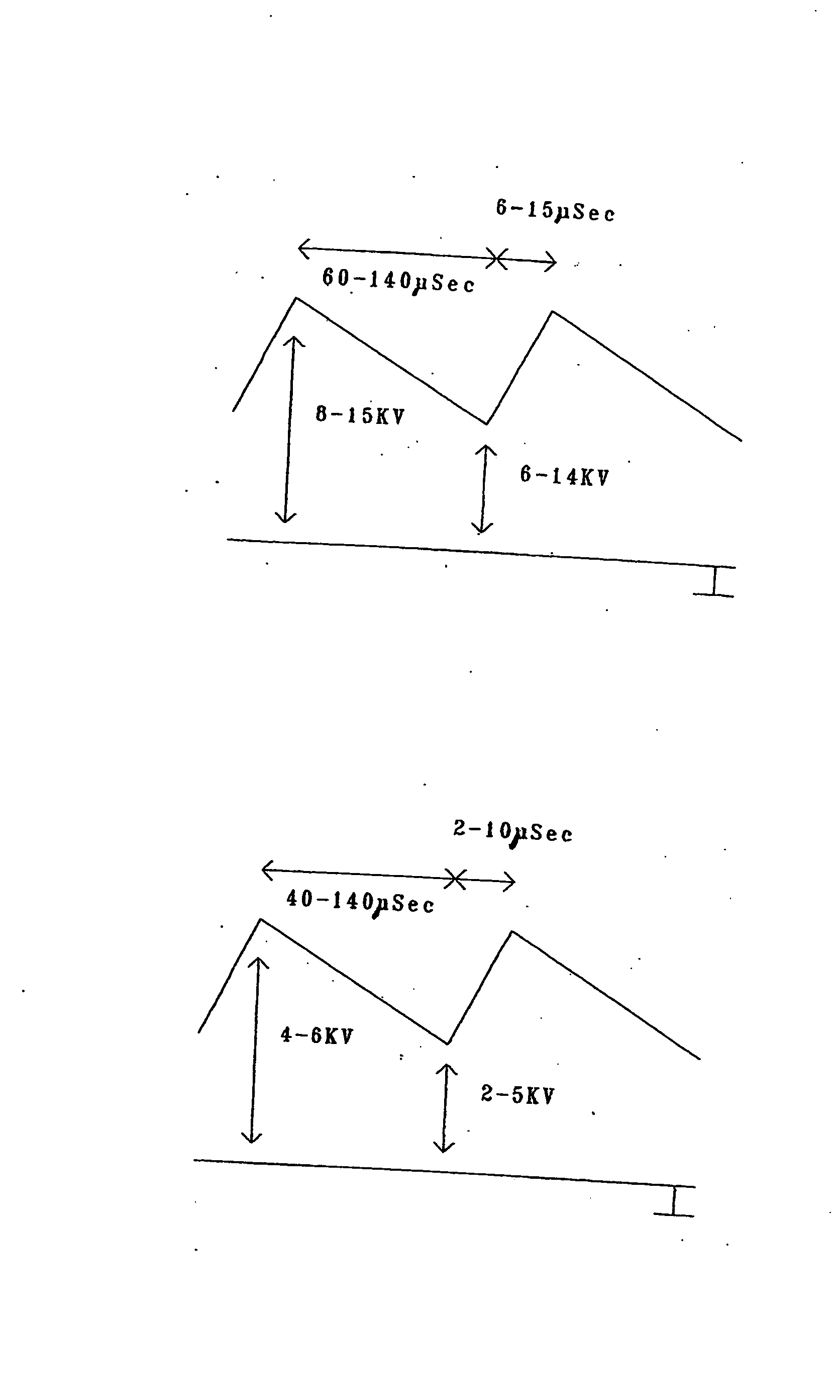
[0011] An exceptionally good control behaviour of this method in accordance with the invention is further obtained by charging the ducts with respect to combusting the exhaust particulate. Since the layer of exhaust particulate deposited in each duct represents a conductor which increases the capacity of the duct, a higher charging and thus a plasma current of longer duration is available for oxidation.
[0012] As a result of the charging of the ducts by means of the unipolar pu

Problems solved by technology

Discharges occur at most within the individual ducts as discharges of the individual ca

Method used


Image

  • Method And Filter Arrangement For Separating Exhaust Particulates
  • Method And Filter Arrangement For Separating Exhaust Particulates
  • Method And Filter Arrangement For Separating Exhaust Particulates

Examples


Embodiment Construction

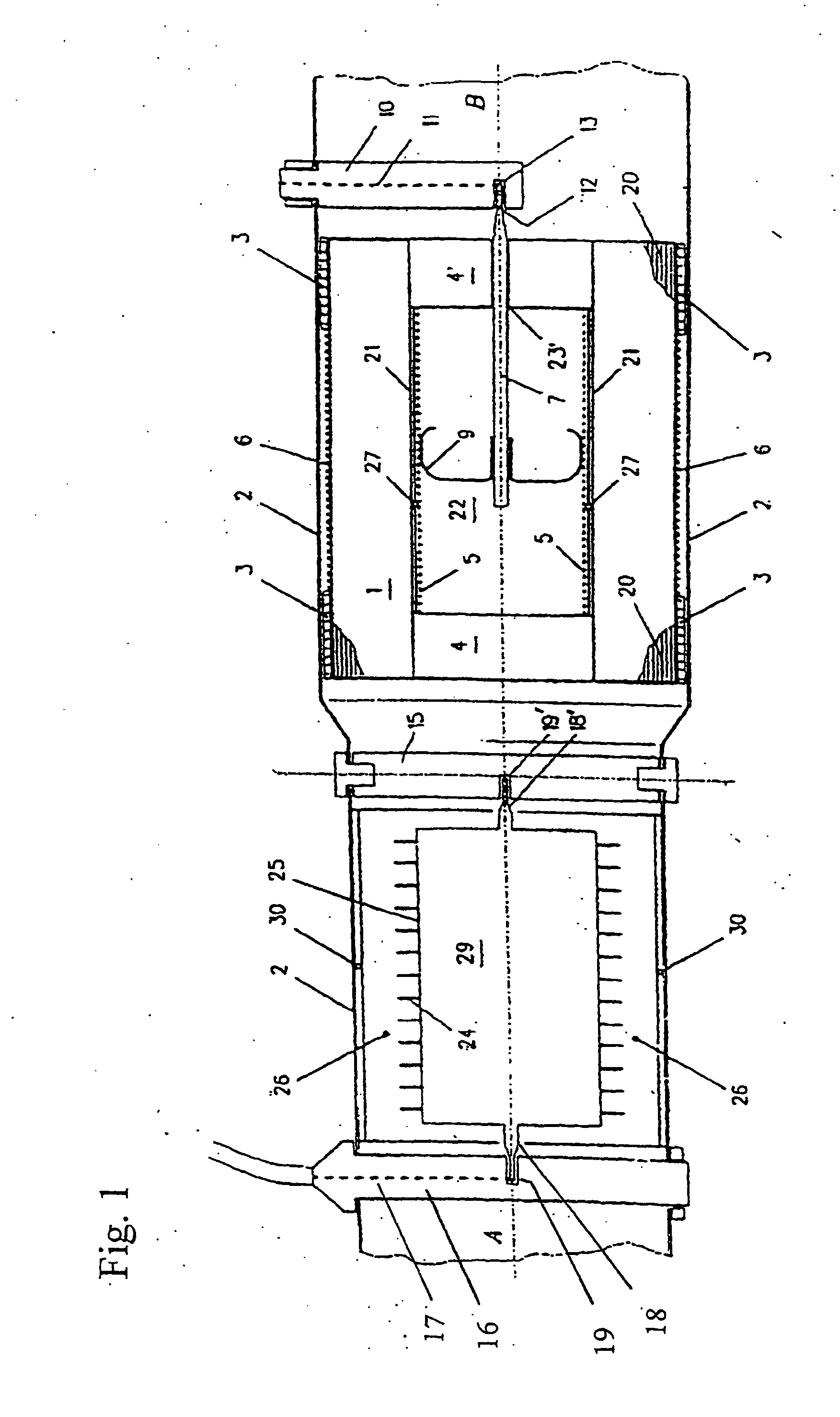
[0030] A possible embodiment of a ceramic body with upstream apparatus for charging exhaust particulates in an exhaust gas stream will be explained for better illustration of the invention by reference to FIG. 1. A ceramic body 1 of annular cross section is fastened by press mats, wire meshes 3 or the like in a cylindrical pipe 2 made of metal. The hollow inside part 22 of the ceramic body 1 is sealed on the inlet side with a non-conductive, preferably ceramic plug 4. An electrically conductive layer is arranged on the inner and outside cylinder jacket of the ceramic body 1, which layer is used as an inner electrode 5 connected to high voltage or as an outer electrode 6 connected to ground. The hollow cavity 22 of the ceramic body 1 is sealed on the outlet side by a non-conductive, preferably ceramic plug 4′. The plug 4′ comprises a thin bore, through which metallic pipe 7 with the thinnest possible diameter is guided, which pipe establishes the contact of the inner electrode 5 with...


PUM


Abstract

A method and apparatus for the operation of a filter arrangement for separating exhaust particulates from an exhaust gas stream, in which the exhaust gas stream is guided through ducts (20) of a ceramic body (1), which ducts extend in the longitudinal direction of a ceramic body (1) and are open on either side, and a voltage is applied to electrodes (5, 6) extending parallel to the ducts (20) in the ceramic body for generating an electric field in the ducts (20) of the ceramic body (1), which field is oriented transversally to the axis of the ducts (20), with a charging of the exhaust particulates occurring by means of a further electrode arrangement (29, 30) prior to the introduction of; the exhaust gas stream into the ducts (20) of the ceramic body (1). It is provided for in accordance with the invention that the voltage applied to the electrodes (5, 6) associated with the ceramic body (1) concerns unipolar voltage pulses which have a pulse duration of less then 20 μs each.

Description

BACKGROUND OF THE INVENTION [0001] 1. Field of the Invention [0002] The invention relates to a method for the operation of a filter arrangement for separating exhaust particulates from an exhaust gas stream, in which the exhaust gas stream is guided through ducts of the ceramic body, which ducts extend in the longitudinal direction of the ceramic body and are open on either side, and a voltage is applied to electrodes extending parallel to the ducts in the ceramic body for generating an electric field in the ducts of the ceramic body, which field is oriented transversally to the axis of the ducts, with a charging of the exhaust particulates occurring by means of a further electrode arrangement prior to the introduction of the exhaust gas stream into the ducts of the ceramic body, in accordance with the preamble of claim 1. [0003] The invention further relates to a filter arrangement for separating exhaust particulates from an exhaust gas stream, comprising a ceramic body with ducts ...

Claims


Application Information

Patent Timeline
IPC IPC(8): B03C3/68B03C3/00
CPCB03C3/68
Inventor FLECK, CARL MARIA
Owner FLECK CARL MARIA
Why Eureka
Try Eureka