Operation of a steam methane reformer by direct feeding of steam rich producer gas from steam hydro-gasification

Inactive Publication Date: 2008-01-24
RGT UNIV OF CALIFORNIA
View PDF3 Cites 17 Cited by
  • Summary
  • Abstract
  • Description
  • Claims
  • Application Information

AI Technical Summary

Benefits of technology

[0012]This invention provides an improved, economical alternative method to supply steam and methane to an SMR. This is accomplished by a combination of new procedures, wherein product gas from an SH

Problems solved by technology

However, s the SMR feed stream needs to be maintained high temperatures, these conventional clean-up techniques are prohibitive from an energy viewpoint, since th

Method used


Image

  • Operation of a steam methane reformer by direct feeding of steam rich producer gas from steam hydro-gasification
  • Operation of a steam methane reformer by direct feeding of steam rich producer gas from steam hydro-gasification

Examples


Embodiment Construction

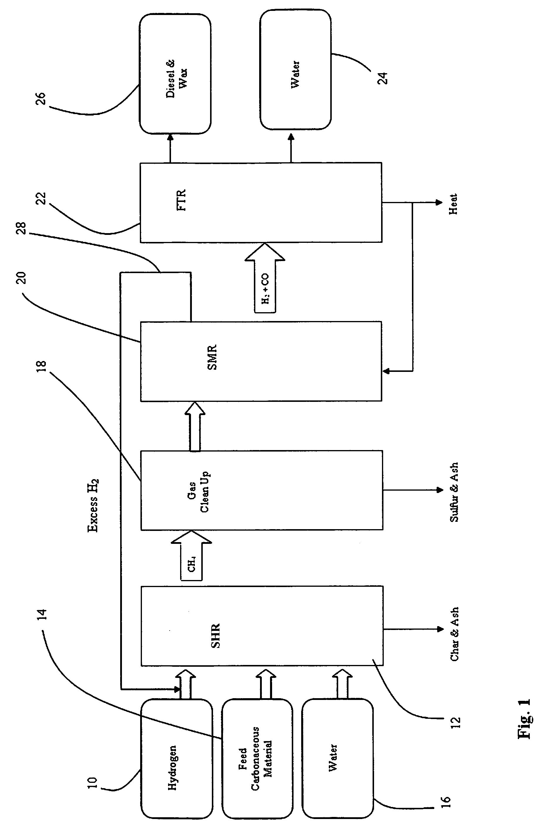
[0020]This invention provides a combination of procedures, where in one embodiment of the invention, the feedstock for an SMR is a mixture of steam and methane rich product gas generated by means of hydro-gasification of a mixture of carbonaceous material and water in an SHR. The steam is present as a result of superheating the water in the feedstock and serves as an ideal feed stream for the SMR.

[0021]The other procedure requires a method of removing impurities from the product stream from the SHR, such as fine particles of ash & char, hydrogen sulfide (H2S) and other inorganic components. These impurities must be removed in order to prevent poisoning of the catalyst used in the SMR while maintaining the SMR feed stream at its high process temperatures. Accordingly, in another embodiment of the invention, a gas cleanup unit is provided that operates at process temperatures and pressures and is located in between the SHR and SMR.

[0022]Referring to FIG. 1, a flow diagram of the proce...


PUM

PropertyMeasurementUnit
Temperatureaaaaaaaaaa
Pressureaaaaaaaaaa

Abstract

An improved, economical alternative method to supply steam and methane to a steam methane reformer (SMR) is accomplished by a combination of procedures, wherein product gas from a steam hydro-gasification reactor (SHR) is used as the feedstock for the SMR by removing impurities from the product stream from the SHR with a gas cleanup unit that operates substantially at process temperatures and pressures and is located between the SHR and SMR.

Description

FIELD OF THE INVENTION[0001]The field of the invention is the synthesis of transportation fuel from carbonaceous feed stocks.BACKGROUND OF THE INVENTION[0002]There is a need to identify new sources of chemical energy and methods for its conversion into alternative transportation fuels, driven by many concerns including environmental, health, safety issues, and the inevitable future scarcity of petroleum-based fuel supplies. The number of internal combustion engine fueled vehicles worldwide continues to grow, particularly in the midrange of developing countries. The worldwide vehicle population outside the U.S., which mainly uses diesel fuel, is growing faster than inside the U.S. This situation may change as more fuel-efficient vehicles, using hybrid and / or diesel engine technologies, are introduced to reduce both fuel consumption and overall emissions. Since the resources for the production of petroleum-based fuels are being depleted, dependency on petroleum will become a major pro...

Claims


Application Information

Patent Timeline
IPC IPC(8): C07C27/06
CPCC01B3/38C10G2300/807C01B2203/0233C01B2203/062C01B2203/1241C01B2203/1258C01B2203/127C01B2203/14C01B2203/148C01B2203/84C10G1/002C10G2400/26C10J3/00C10J2300/093C10J2300/0966C10J2300/0973C10J2300/1659C10J2300/1853Y02E50/32C10K1/024C10K1/143C10K1/16C10K1/165C10K3/00C10G2300/1003C10G2300/1011C01B31/18C01B32/40Y02E50/30Y02P30/20
Inventor NORBECK, JOSEPH M.PARK, CHAN SEUNG
Owner RGT UNIV OF CALIFORNIA
Why Eureka
Try Eureka