
Thin tube which can be hyperflexed by light

a technology of light and flection, applied in the field of thin tubes, can solve the problems of changing the flection of the forward end of the catheter, requiring skill and time-consuming operation, and requiring complex mechanisms, so as to prevent the leakage of electric current, and be easily and quickly operated.

Inactive Publication Date: 2008-01-24
KEIO UNIV
View PDF18 Cites 106 Cited by
  • Summary
  • Abstract
  • Description
  • Claims
  • Application Information

AI Technical Summary

Benefits of technology

[0013] As described above, in the cases of the above conventional catheters, the forward end of which can be controlled, a complicated mechanism is necessary. In addition, operation of such forward end requires skills and is time-consuming. Further, in a case of a catheter in which a shape-memory alloy is used such that it becomes possible to operate the forward end, it is necessary to allow an electric current to flow into the shape-memory alloy. Thus, strict insulating is necessary for preventing leakage of electric current.
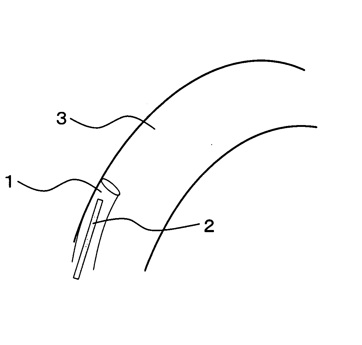
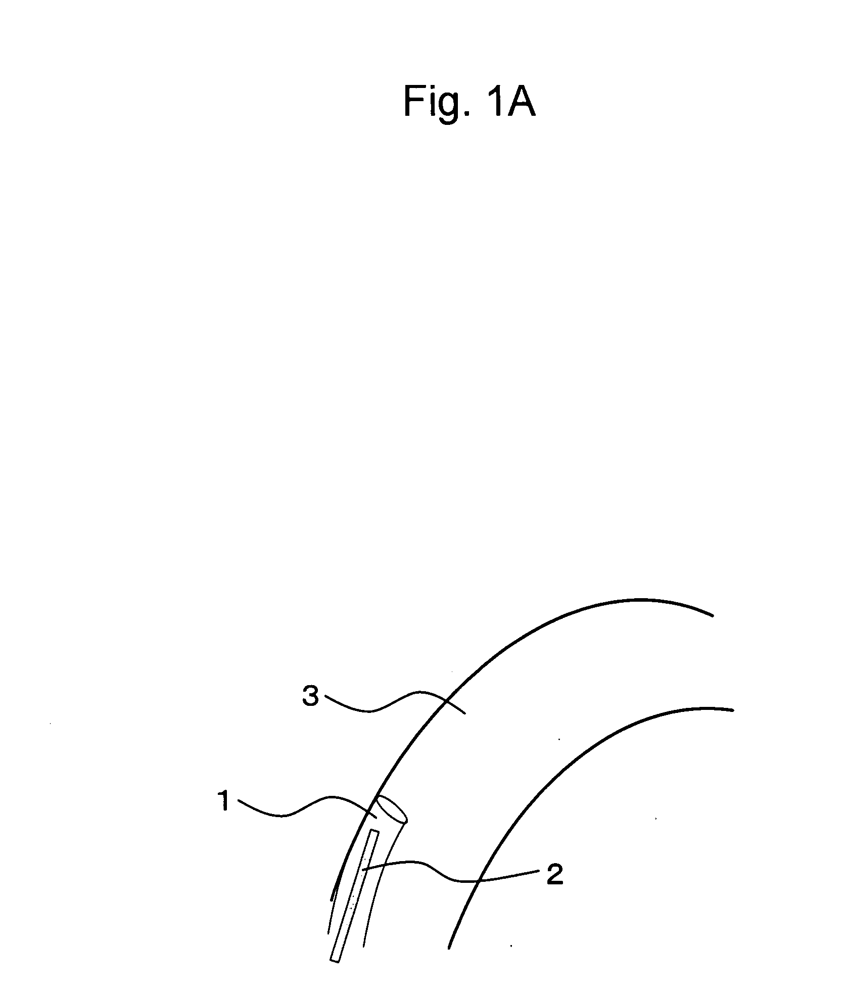
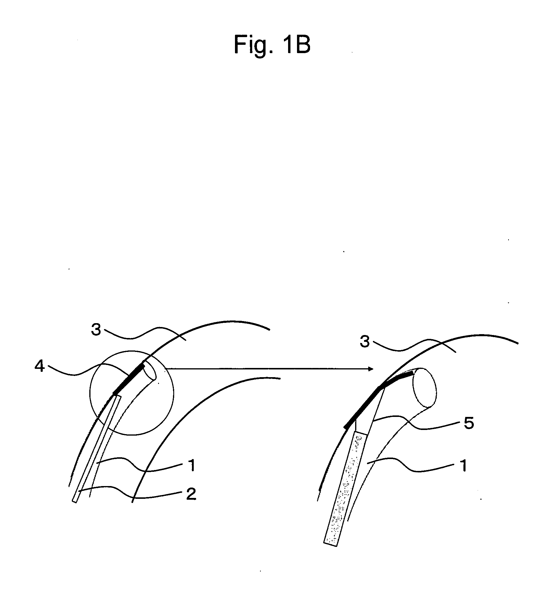
[0014] The inventors of the present invention have made intensive studies of a thin tube such as a catheter with a forward end that can readily and rapidly be operated. When the flexed forward end of a catheter is irradiated with light, the inner wall (opposite to the side to which the forward end is flexed) of the flexed forward end of the catheter is exposed to light. The inventors of the present invention have found that the flexed direction of the forward end of a catheter can be detected in such case by measuring light or temperature increases at a site exposed to light upon light irradiation. Further, the present inventors have found that it is possible to deform the shape of the forward end of a catheter and control the flection of the forward end of the catheter so as to control the traveling direction of the catheter with the use of a material that can be deformed by light and heat generated upon light irradiation. For instance, when a catheter is inserted into a lumen, the forward end of the catheter comes into contact with the bending section of the lumen so as to become lightly flexed. In such case, a means of irradiating the inside of a lumen of a catheter with light, such as a laser or the like, is provided in a manner such that light irradiation takes place in the traveling direction of the catheter. Thus, light irradiation is performed when the forward end of the catheter is lightly flexed so that a part of the inner wall of the catheter (such part being located opposite to the side to which the forward end of the catheter has been flexed) is always irradiated with light. Thus, a material (light-absorbing material) that generates heat by absorbing light and a material (deformable material) the shape or the volume of which varies depending on heat are disposed at a position subjected to light irradiation in a manner such that they are allowed to come into contact with each other for heat conduction. Accordingly, heat generated upon light irradiation changes the shape of such deformable material, resulting in change in flection of the forward end of the catheter. Therefore, it becomes possible to regulate the traveling direction of the catheter.
[0019] the inner thin tube comprises a deformable material that can be deformed by light irradiation so as to serve as an actuator that is operated via irradiation of light from the forward end, and the deformable material is deformed by the action of light irradiated from a light transmission means in the thin tube, so that the forward end of the thin tube can be flexed;
[0025] the inner thin tube comprises a deformable material that can be deformed by light irradiation so as to serve as an actuator that is operated via irradiation of light from the forward end, and the deformable material is deformed by the action of light irradiated from a light transmission means in the thin tube, so that the forward end of the thin tube can be flexed;

Problems solved by technology

As described above, in the cases of the above conventional catheters, the forward end of which can be controlled, a complicated mechanism is necessary.
In addition, operation of such forward end requires skills and is time-consuming.
Accordingly, heat generated upon light irradiation changes the shape of such deformable material, resulting in change in flection of the forward end of the catheter.

Method used


Image

  • Thin tube which can be hyperflexed by light
  • Thin tube which can be hyperflexed by light
  • Thin tube which can be hyperflexed by light

Examples


example 1

Experiment of Allowing a Thin Tube Flexed

[0147] A tube 9 mm in inner diameter (Sanyo Rikagaku Kikai Seisakusho) was spirally coiled. A bimetal was attached to a single site on the outer side of the tube. The bimetal used was BR-1 (size: 4 mm×60 mm, NEOMEX). The bimetal was attached in a manner such that the high-expansion metal thereof was disposed on the outside of the tube. Irradiation with a semiconductor laser (3 W) was conducted from the inside and outside of the tube. The laser-generating device used was UDL-60 (OLYMPUS). FIGS. 4 and 5 show experiments of laser irradiation from the inside of the tube. FIGS. 6 and 7 show experiments of laser irradiation from the outside of the tube. FIGS. 4 and 6 show the tube before laser irradiation. FIGS. 5 and 7 show the tube immediately after laser irradiation. In FIGS. 4 to 7, the bimetal is shown as a stick attached to the upper part of the tube. In FIGS. 5, 6, and 7, a tube-like thin stick is an optical fiber used for laser irradiation...

example 2

Experiment of Allowing a Thin Tube Flexed in a Lumen

[0148] A tube 38 mm in inner diameter was used as a simulated blood vessel. The simulated blood vessel was curved so as to be immobilized in that state. Then, an experiment similar to that conducted in Example 1 was carried out in the simulated blood vessel.

[0149] The tube 9 mm in inner diameter to which a bimetal had been attached used in Example 1 was inserted into the simulated blood vessel in a curved state. The tube was allowed to be flexed in a direction parallel to the direction of the curvature of the simulated blood vessel (FIG. 8).

[0150] Under such condition, irradiation with a semiconductor laser (3.5 W) from a fiber 750 μm in inner diameter and 1 mm in outer diameter that had been inserted into the tube was performed. FIG. 9 shows results of the irradiation. As shown in FIG. 9, the tube to which a bimetal had been attached further flexed in a direction identical to the bending direction of the simulated blood vessel....

example 3

Experiment of Measuring the Temperature of a Tube

[0151] Upon irradiation with a semiconductor laser (3 W) from a fiber 750 μm in inner diameter and 1 mm in outer diameter that had been inserted into a tube 9 mm in inner diameter, temperatures of the following sites were measured using a thermocouple (TS-T-36-1, Ishikawa Trading Co., Ltd.). The measurement of temperature was performed at the site at which laser irradiation was performed, a site located at a distance of ¼ of the circumference of the tube from the irradiation site, and a site located at a distance of ½ of the circumference of the tube from the irradiation site.

[0152]FIG. 10 shows results of the measurement obtained at the site of laser irradiation and at the site located at a distance of ½ of the circumference of the tube from the irradiation site. FIG. 11 shows results of the measurement obtained at the site of laser irradiation and at the site located at a distance of ¼ of the circumference of the tube from the irr...


PUM


Abstract

A thin tube is provided that is inserted into a lumen of a living body so as to be used, which can detect the flexed direction of the forward end of itself with the use of a sensor disposed at such forward end upon light irradiation. The forward end of the thin tube is allowed to be flexed to a desired direction with the use of an actuator disposed at such forward end. Such thin tube for medical use is inserted into the lumen of a living body so as to be used for internal observation or internal treatment and contains a device for sensing light irradiation and / or an actuator that is operated via light irradiation at its forward end and a light transmission means, such light transmission means being used for irradiating the device and / or the actuator with light and such device or actuator functioning for monitoring and / or controlling the degree of flection of the forward end of such thin tube, is provided.

Description

BACKGROUND OF THE INVENTION [0001] 1. Field of the Invention [0002] The present invention relates to a thin tube that is inserted into a lumen of a living body, such as a blood vessel, for observation and treatment of the inside of such lumen, for example. In particular, the present invention relates to a catheter that is inserted into tubular organs of a living body for use, such organs including blood vessels and digestive tracts. [0003] 2. Background Art [0004] Hitherto, thin tubes such as catheters and the like have been used when an endoscope or the like is used for observation, diagnostics, or the like of the inside of a lumen of a living body such as a blood vessel, a digestive tract, a urinary tract, an ovarian duct, and trachea, or for therapies or the like involving internal observation and internal treatment. For instance, in order to insert a catheter into a lumen of a living body such as a blood vessel which is tortuous and branches in a complicated manner and guide the...

Claims


Application Information

Patent Timeline
Patent Type & Authority Applications(United States)
IPC IPC(8): A61M23/00
CPCA61B1/0051A61B1/0052A61B1/0055A61M25/0054A61B1/00167A61M25/0158A61M2025/0064G02B23/2476A61B1/07A61M25/0074
Inventor ARAI, TSUNENORISUGA, ERIKOYAMASHITA, ERIKA
Owner KEIO UNIV
Learn More