
System and method for dispensing an aqueous urea solution into an exhaust gas stream

a technology of aqueous urea and aqueous solution, which is applied in the direction of machines/engines, engine components, mechanical apparatus, etc., can solve the problems of current urea injection system, overheating and potential valve plugging, and other problems inherent in the system

Active Publication Date: 2008-01-31
SOUTHWEST RES INST
View PDF25 Cites 74 Cited by
  • Summary
  • Abstract
  • Description
  • Claims
  • Application Information

AI Technical Summary

Benefits of technology

[0014]In yet another aspect of the present invention, a method for injecting an aqueous urea solution into an exhaust gas stream includes providing a source of pressurized solution of urea and water and a source of compressed air. The pressurized solution of urea and water are conveyed through a first elongated tube. A continuous flow of compressed air is conveyed an annular space defined between a second elongated tube concentrically disposed in circumscribing relationship around the first elongated tube and into a mixing chamber defined between spaced apart distal ends of the first and second elongated tubes. The pressurized solution of urea and water is discharged from the distal end of the first elongated tube into a mixing chamber that gets into the mixing chamber in a series of modulated discreet pulsed injections. The discharged pressurized solution of urea and water is mixed with the compressed air in the mixing chamber. A back flow of the mixed solution of urea and water with compressed air from the mixing chamber into the first elongated tube is prevented during the period between each of the discreet pulsed injections. The mixed solution of urea and water with compressed air is sprayed from the mixing chamber through a plurality of openings provided in the distal end of the second elongated tube and into the exhaust gas stream.

Problems solved by technology

However, there are several problems associated with current urea injection systems.
For example, in the above-referenced Amou, et al. arrangement, the urea injection valve is directly mounted on a surface that conducts the exhaust gas and is therefore prone to overheating and potential plugging of the valve.
Other problems also are inherent in current systems used to inject urea-water mixtures into an elevated temperature exhaust gas.
More specifically, the spray of the urea-water mixture does not flow uniformly from multiple holes in the tip of an atomizer positioned in an exhaust pipe, especially at low dosing rates.
Furthermore, urea solution supply systems positioned in the exhaust system tend to plug due to partial evaporation of the water in the supply tube between the dosing valve and the atomizer tip.
Slugs of urea-water mixture migrate through the supply tube and tend to preferentially spray out of only one or two of the several holes provided in the atomizer tip, a condition particularly troublesome at low liquid flow rates.

Method used


Image

  • System and method for dispensing an aqueous urea solution into an exhaust gas stream
  • System and method for dispensing an aqueous urea solution into an exhaust gas stream
  • System and method for dispensing an aqueous urea solution into an exhaust gas stream

Examples


Embodiment Construction

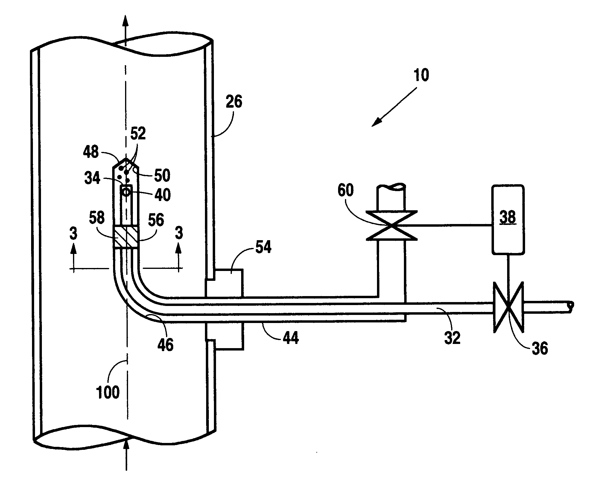
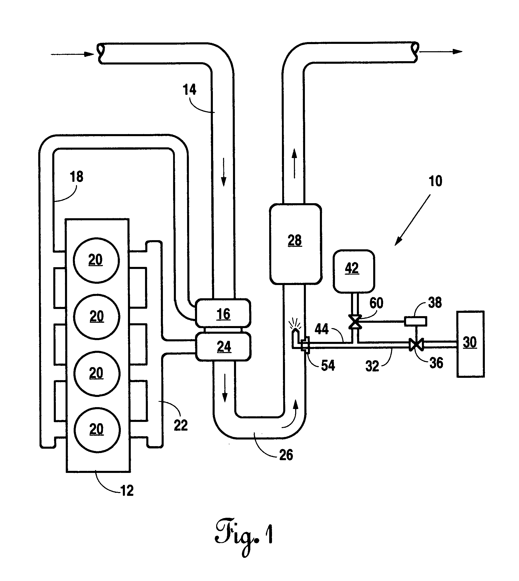
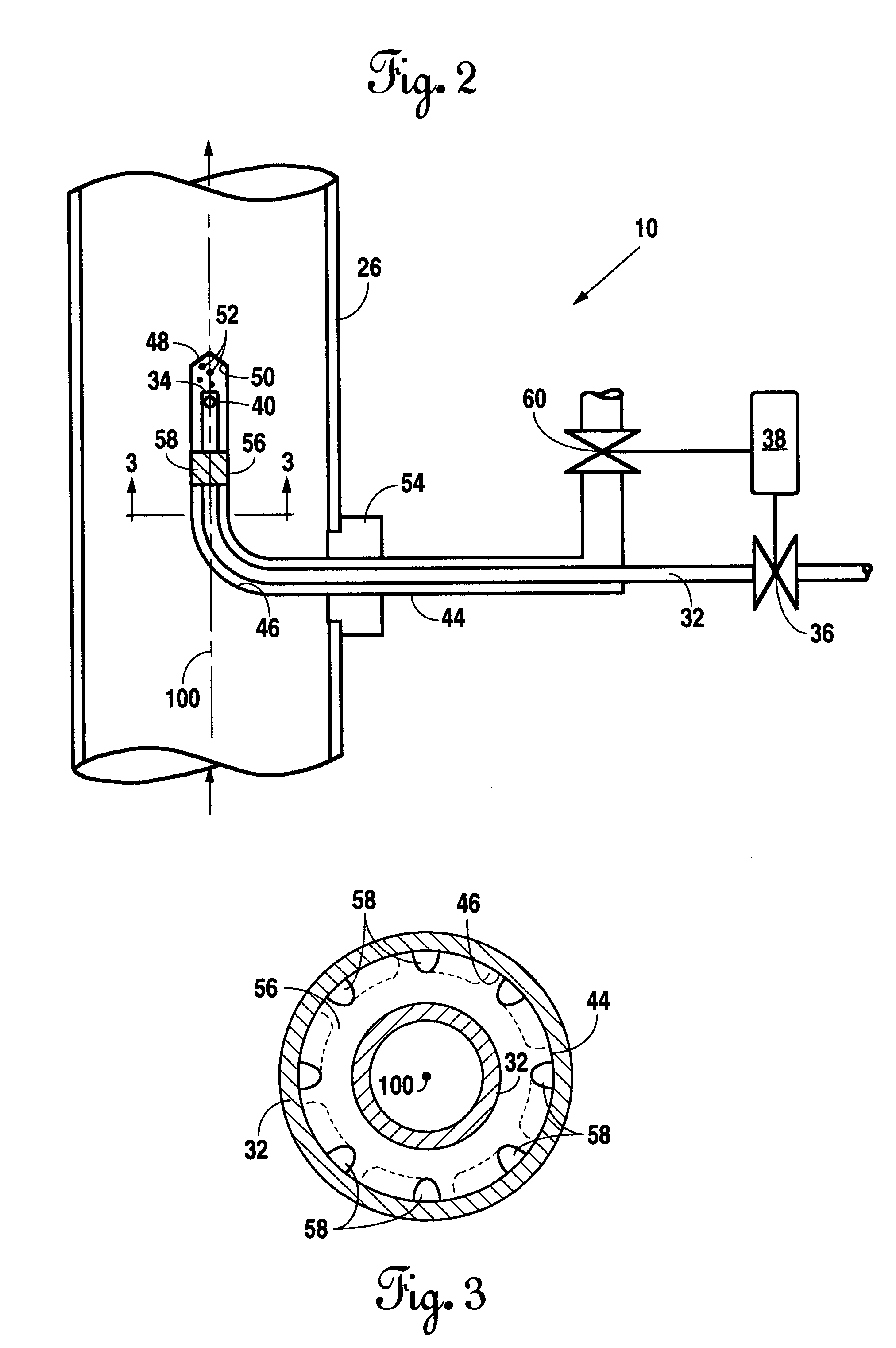
[0022]A preferred embodiment of the system for dispensing an aqueous urea solution into an exhaust gas stream is illustrated in FIGS. 1-3. In FIG. 1, an illustrative application for a system for dispensing an aqueous urea solution in an exhaust gas stream, in accordance with the present invention, is generally indicated by the reference numeral 10. In the illustrative application, the system 10 is used to dispense an aqueous urea solution into the exhaust stream of a conventional diesel engine 12. In the simplified illustrated application, the diesel engine 12 has an air intake duct 14 through which an intake air charge is inducted into a compressor stage 16 of a turbocharger and then conducted through an intake manifold 18 into a plurality of combustion chambers 20. The intake air charge is mixed with fuel in the combustion chambers 20, combusted and discharged through an exhaust manifold 22 into a turbine stage 24 of the turbocharger. After discharge from the turbocharger 24, the ...


PUM


Abstract

An aqueous urea dosing system has a first tube through which the urea solution is conveyed to a small mixing chamber. Compressed air is continuously conveyed through an annular space between the outer surface of the first tube and the inner surface of a second tube which has a distal end that extends beyond a distal end of the first tube. The mixing chamber is positioned between the respective distal ends of the first and second tubes. The urea solution is discharged into the small mixing chamber, and subsequently immediately into an exhaust gas, in a series of discreet pulses, the width and period of which are controlled by a pulse-width-modulated flow control valve spaced from the exhaust gas.

Description

BACKGROUND OF THE INVENTION[0001]1. Technical Field[0002]This invention relates generally to a system and method for dispensing aqueous solutions into an elevated temperature environment, and more particularly, to such a system and method for injecting an aqueous urea solution into an exhaust gas stream.[0003]2. Background Art[0004]The selective catalytic reduction (SCR) of NOx using ammonia or urea has been used for many years in industrial processes. For example, U.S. Pat. No. 4,985,218 granted Jan. 15, 1991 to Vincent A. DeVita for a SYSTEM FOR INJECTING A TREATMENT FLUID, SUCH AS A UREA AND WATER SOLUTION, INTO THE EXHAUST DUCT OF A STATIONARY INDUSTRIAL BOILER.[0005]The U.S. Protection Agency (EPA) has set very stringent standards directed toward reducing NOx and other undesirable emissions from vehicular as well as stationary engines, and urea injection upstream of an SCR catalyst has been proposed as one way to reduce NOx emissions from vehicular engines. For example, U.S. Pu...

Claims


Application Information

Patent Timeline
Patent Type & Authority Applications(United States)
IPC IPC(8): F01N3/00
CPCF01N3/2066F01N2610/02Y02T10/24F01N2610/1453F02B37/00F01N2610/08Y02T10/12
Inventor DODGE, LEE G.KUNKEL, PAUL H.
Owner SOUTHWEST RES INST
Features
  • Generate Ideas
  • Intellectual Property
  • Life Sciences
  • Materials
  • Tech Scout
  • Unparalleled Data Quality
  • Higher Quality Content
  • 60% Fewer Hallucinations
Learn More