Aerodynamic Lens Particle Separator

a technology of aerodynamic lens and particle separator, which is applied in the direction of gas current separation, separation process, instruments, etc., can solve the problems of large difficulty in precisely aligning a series of such small openings, the flow rate of such a device is still extremely small, and the maximum flow rate that can be accommodated by such small openings is extremely small

Active Publication Date: 2008-01-31
ENERTECHNIX
View PDF1 Cites 22 Cited by
  • Summary
  • Abstract
  • Description
  • Claims
  • Application Information

AI Technical Summary

Benefits of technology

[0012] Placing a skimmer at the exit of each micro-fabricated lens in the assembly allows the bulk of the gas flow to be stripped off while allowing the concentrated particle stream to pass into a region of much lower flow rate, thereby producing a highly concentrated aerosol in the low velocity stream.

Problems solved by technology

The small size of this orifice or slit creates two practical problems.
First, accurately machining components with such small dimensions by traditional methods can be accomplished only by using specialized techniques such as laser cutting or drilling or electric discharge machining (EDM), and precisely aligning a series of such small openings is a major challenge if they are fabricated as separate components and then combined into a single assembly.
Second, the maximum flow rate that can be accommodated by such small openings is extremely small.
The use of a slit lens instead of a circular orifice provides some improvement in flow rate due to the substantially greater cross sectional area of the opening, but the flow rates for such a device are still extremely small.

Method used


Image

  • Aerodynamic Lens Particle Separator
  • Aerodynamic Lens Particle Separator
  • Aerodynamic Lens Particle Separator

Examples


Embodiment Construction

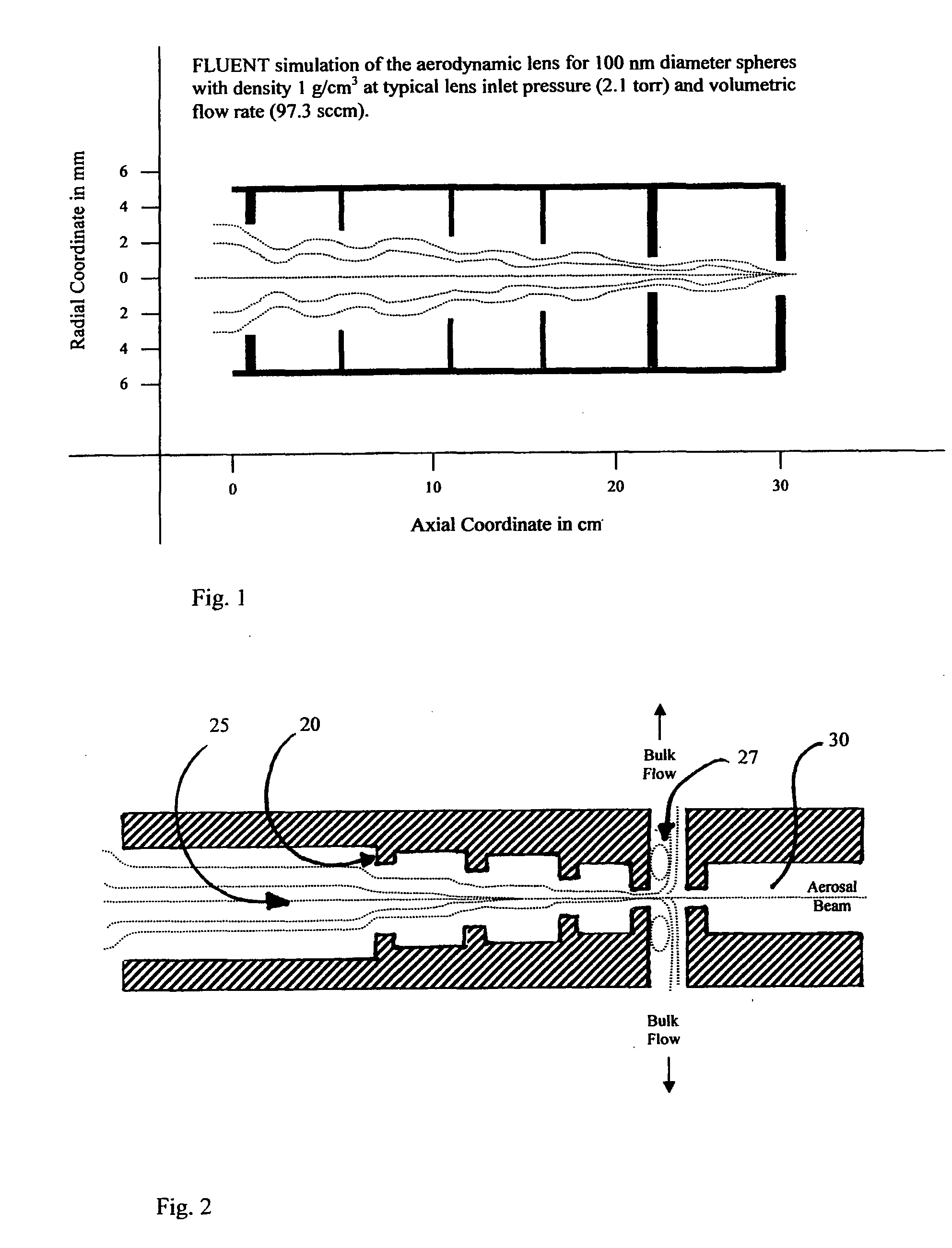
[0021] Turning now to the drawings, wherein like reference characters designate identical or corresponding parts, and more particularly to FIG. 2 thereof, an aerodynamic aerosol particle separator is shown having a train of four slit lenses in series. Each lens includes a slit baffle 20 projecting laterally into a longitudinal channel 25. The channel 25 becomes progressively narrower at each lens and the slit in each baffle also becomes narrower for each successive lens. A skimmer 27 just upstream of a collection chamber 30 allows for exit of clean air from the particle-entraining air flow, as shown. The light lines depict fluid streamlines and the darker stream lines depict particle trajectories.

[0022] In FIG. 3, a micro-fabricated array of two parallel aerosol particle separator slit lens trains 35 and 40 is shown having channels 42 and 43 extending through a fabricated structure 45. An aerosol flows through the channels 42 and 43 in the direction indicated by the arrows. Aerosol...


PUM

PropertyMeasurementUnit
particle diametersaaaaaaaaaa
diameteraaaaaaaaaa
diametersaaaaaaaaaa

Abstract

Respirable particles with diameters on the order of 0.05 to 10 microns entrained in an air stream. are concentrated in an aerodynamic lens (FIG. 2) for separation from the air steam. The entire structure is made by microfabrication techniques, such as silicon micro-machining which enables arrays of precisely aligned slit lenses to be made on a silicon chip. At a Reynolds number of 800, a slit 25 microns wide by 1 mm tall will pass a flow of only 0.28 liters per minute, but arrays of lenses (FIG. 4), stacked in parallel banks, multiplies the available flow rate. Placing a skimmer (27) at the exit of each silicon micro-machined lens in the assembly and connecting the skimmer channels in chimneys (55), allows the bulk of the gas flow to be stripped off while allowing the concentrated particle stream to pass into a region of much lower flow rate, thereby producing a highly concentrated aerosol in the low velocity stream.

Description

[0001] This invention pertains to concentration of particles suspended in a gas stream, and more particularly to an aerodynamic lens device for separation of suspended particles from a gas stream to collect the particles for testing or the like, or for producing a gas stream that is substantially free of suspended particles in a particular size range. BACKGROUND OF THE INVENTION [0002] Atmospheric aerosols from natural, anthropogenic and industrial sources have long been recognized as a potential threat to human health. To that list of sources, chemical or biological warfare (CBW) agents due to acts of terrorism must now be added as a source of potentially lethal contamination. Effective sampling and concentration of CBW agents is a critical first step in the detection of these aerosols, and much effort has gone into developing effective methods for rapid screening and detection of CBW agents in samples which can then be analyzed to assess the risk of exposure to these aerosols. One...

Claims


Application Information

Patent Timeline
Patent Type & Authority Applications(United States)
IPC IPC(8): B01D45/08B21D39/00G01N1/22G01N15/02H01J41/04
CPCG01N1/2202Y10T29/49826G01N15/0255G01N1/2208B33Y80/00
Inventor ARIESSOHN, PETER
Owner ENERTECHNIX
Why Eureka
Try Eureka