
Bonding apparatus and method for cleaning tip of a bonding tool

Active Publication Date: 2008-01-31
SHINKAWA CO LTD
View PDF7 Cites 40 Cited by
  • Summary
  • Abstract
  • Description
  • Claims
  • Application Information

AI Technical Summary

Benefits of technology

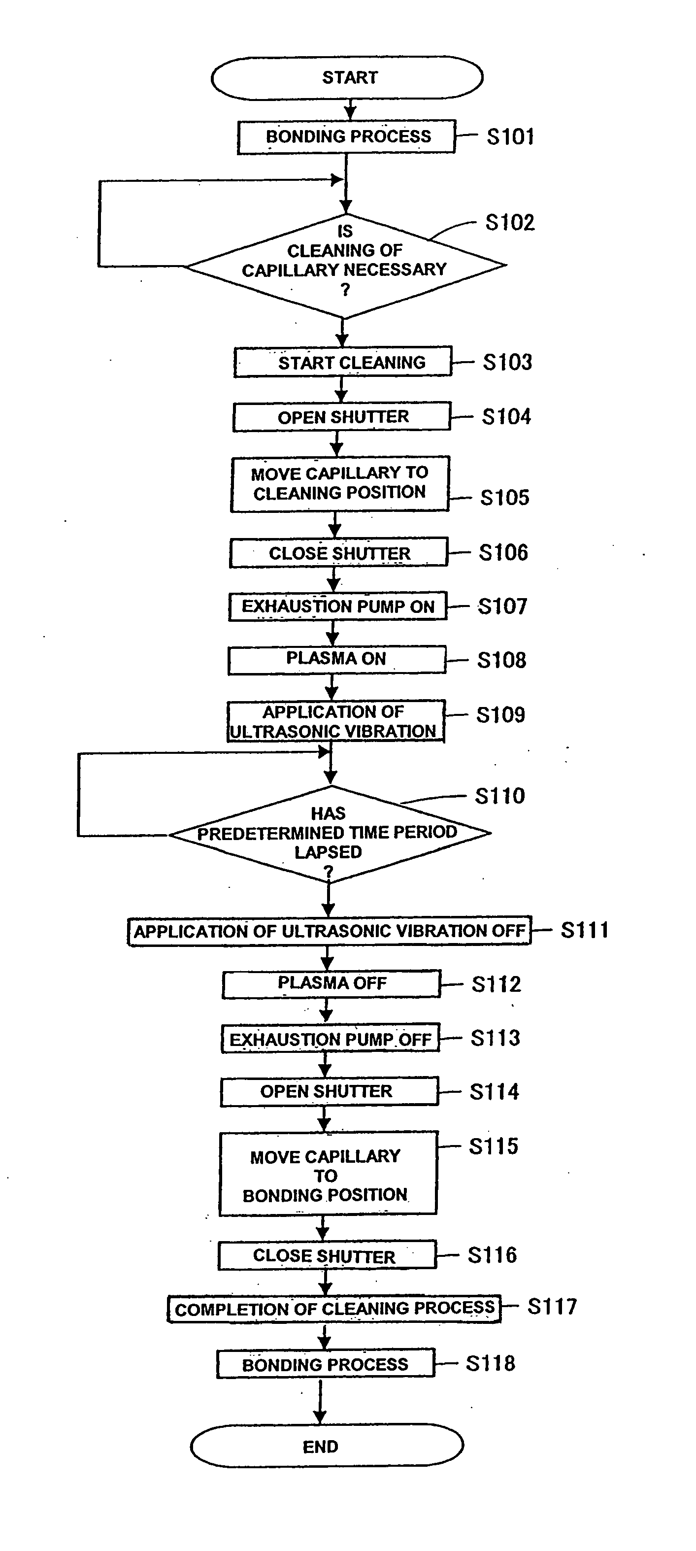
[0017] Accordingly, it is an object of the present invention is to provide a bonding apparatus and method which can effectively clean the foreign substances that have attached to a tip of a bonding tool.
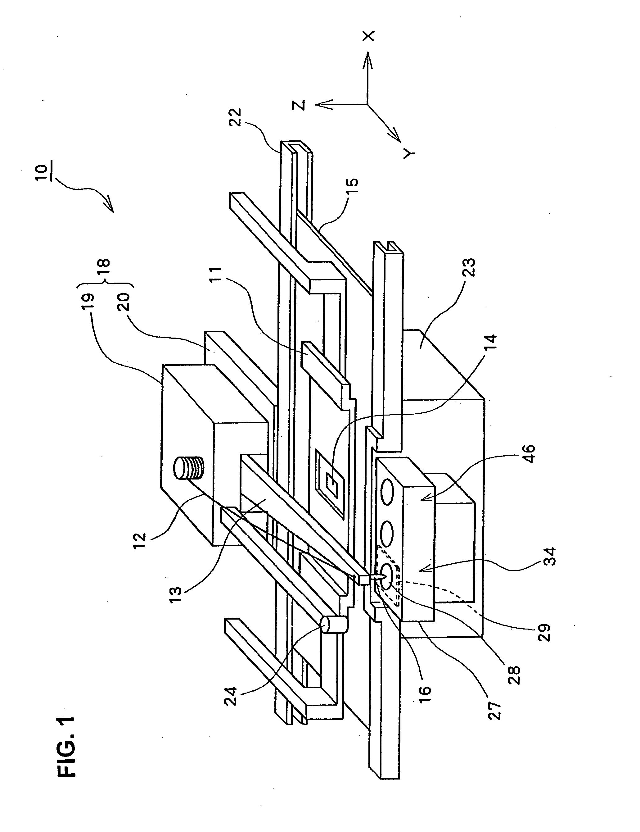
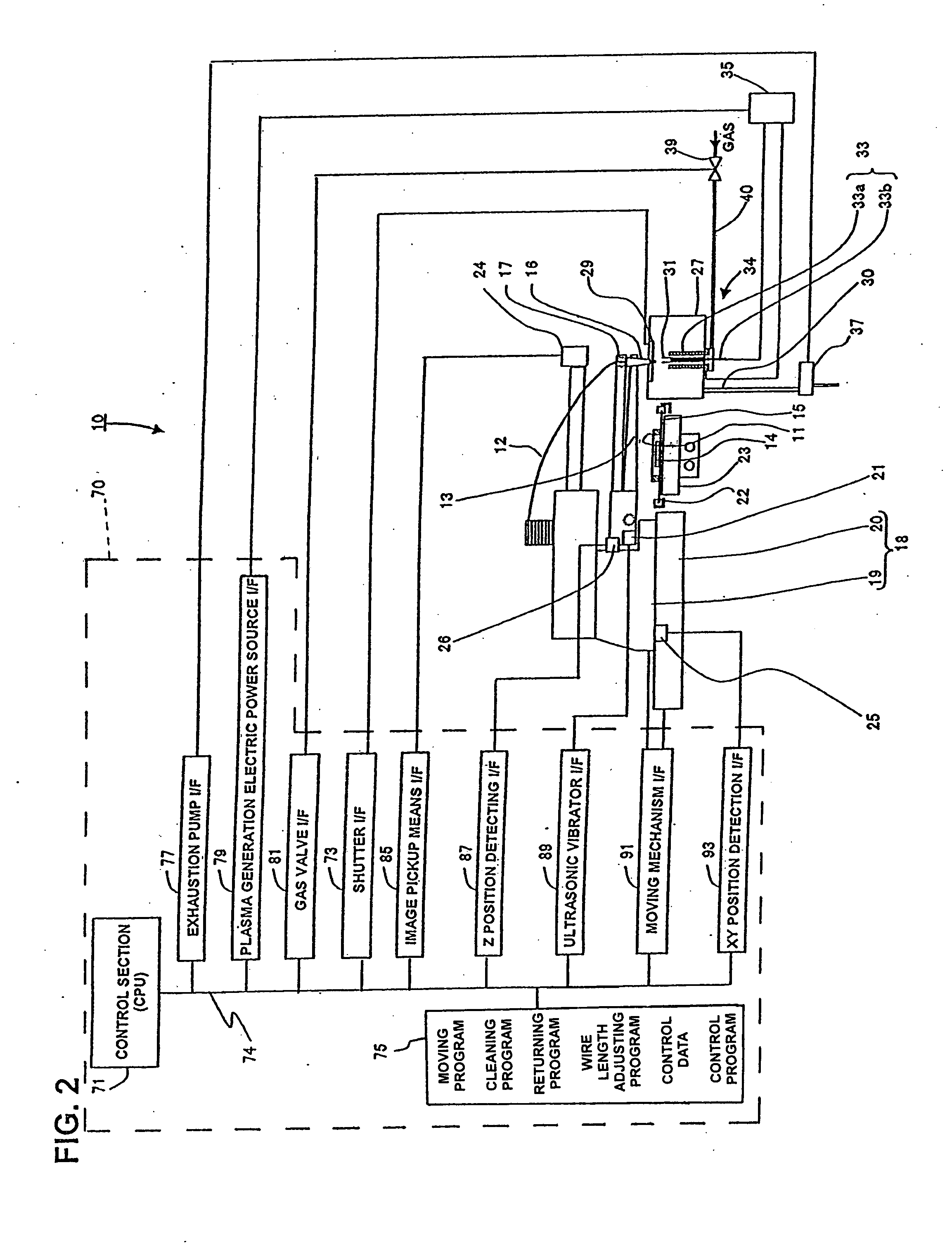
[0020] It is preferable that the bonding apparatus is provided with a shutter for closing the gap between the bonding tool and the opening when the tip of the bonding tool is inserted into the cleaning case through the opening. It is also preferable that the bonding apparatus is provided with a gas exhaustion pump for exhausting after-cleaning gas from the cleaning case through the exhaust port.
[0029] As seen from the above, the bonding apparatus and method according to the present invention has an advantage that foreign substances attaching to the tip of the bonding tool are effectively removed. The bonding apparatus and method according to the present invention has another advantage that the cleaning of the bonding tool can be carried out successively during the bonding operation.

Problems solved by technology

In the bonding apparatus as mentioned above, it is likely that foreign substances attach to the surface of the bonding tool while the bonding operation is repeated for about five hundred thousands of times to one million times. Those foreign substances can cause defects in the bonding.
The metallic foreign substances mainly attached to the portion close to the corner at the intersection of the chamfer portion 53 and the face portion 54 are liable to make it difficult for the corner to sink into the wire and cause inconvenience in cutting of the wire after bonding process.
However, this conventional technology has a problem that it can not effectively remove the foreign substances since the tungsten wire 65 does not make contact with the foreign substances attaching to the inner wall of the chamfer portion 53.
Consequently, the inconvenience for cutting the wire after bonding was occasionally caused even though the cleaning was done.
As a result, this conventional technology has a problem that the cleaning of the capillary 16 cannot be carried out successively together with the bonding process.
Especially, as it is often the case that several tens of bonding machines are operated simultaneously, this conventional technology has another problem.
As discussed above, it is difficult for the conventional technologies to effectively clean the foreign substances that have attached to the tip of the bonding tool.
It is also difficult for the conventional technologies to carry out the cleaning of the bonding tool successively during the bonding process.

Method used


Image

  • Bonding apparatus and method for cleaning tip of a bonding tool
  • Bonding apparatus and method for cleaning tip of a bonding tool
  • Bonding apparatus and method for cleaning tip of a bonding tool

Examples


second embodiment

[0073] the present invention will now be described with reference to FIGS. 6 and 7. In FIGS. 6 and 7, components or parts that are the same as or similar to those of the embodiment shown in FIGS. 3(a) and 3(b) are denoted by the same reference numerals or marks, and the explanation of them is omitted.

[0074] As seen from FIG. 6, in the structure of the second embodiment, a plurality of plasma torches 31 each having a plasma nozzle 38 are provided, and it further includes capacitive coupling electrodes 33 composed of an outer electrode 33a and an inner electrode 33b; and each plasma nozzle 38 is arranged such that the center line 31a of the plasma nozzle 38 is directed to the intersection of the longitudinal center line 59 of the capillary 16 and the end plane of the capillary. With this arrangement, the microplasma 32 is ejected from below the capillary tip portion 16a in slanting direction to the chamfer portion 53, the straight hole 55, the face portion 54, the outer radius portion...

third embodiment

[0085]FIG. 9 shows the present invention. In FIG. 9, the components or parts that are the same as or similar to those of the embodiment shown in FIGS. 6 and 7 are denoted by the same reference numerals or marks, and the explanation of them is omitted.

[0086] As shown in FIG. 9, the microplasma generating section 34 is fixed on a rotary base plate 50 which in turn is installed on the bottom surface of the cleaning case 27. The plasma nozzle 38 is arranged such that its center line 31a is directed to the intersection of the longitudinal center line 59 of the capillary 16 and the end plane of the capillary 16. The angle made by the center line 31a of the plasma nozzle (or the plasma torch 31) and the longitudinal center line 59 of the capillary 16 is θ. The rotary base plate 50 rotates around the longitudinal center line 59 of the capillary 16. With this arrangement, the microplasma 32 is ejected to the capillary tip portion 16a from below in the slanted direction all around the capilla...


PUM

PropertyMeasurementUnit
Lengthaaaaaaaaaa
Electric propertiesaaaaaaaaaa

Abstract

A wire bonding apparatus for manufacturing, for instance, semiconductor devices, including a cleaning case in which a microplasma generating section comprised of a plasma torch, which has a plasma nozzle 38 at the end, and capacitive coupling electrodes composed of an outer electrode and an inner electrode is fixed to the bottom of the cleaning case. The plasma nozzle is provided such that its center line is in alignment with the longitudinal center line of the capillary. Microplasma is ejected from below the capillary to clean its tip within the cleaning case. A shutter is provided on the top of the cleaning case and the wasted gas produced as a result of cleaning is exhausted out of the cleaning case through an exhaustion port of the cleaning case.

Description

BACKGROUND OF THE INVENTION [0001] The present invention relates to a structure of a bonding apparatus and a method for cleaning a tip of a bonding tool installed in the bonding apparatus. [0002] In a process of manufacturing semiconductor devices, a wire bonding apparatus is used for connecting leads of a lead frame with pads of a semiconductor die mounted on the lead frame. When this connection is made, a bonding tool such as a wedge tool, a capillary or the like is used for sequentially pressing metal wires respectively against the pads and their corresponding leads and combining the metal wire with the pads and the leads. In other case, a bump bonding apparatus bonds wires onto bonding pads of a semiconductor chip to form bumps likely as in the case of the wire bonding. [0003] In the bonding apparatus as mentioned above, it is likely that foreign substances attach to the surface of the bonding tool while the bonding operation is repeated for about five hundred thousands of times...

Claims


Application Information

Patent Timeline
IPC IPC(8): B08B7/00B23K3/00B23K37/00
CPCB08B7/0035B23K20/004H01L2224/45147H01L2224/48247H01L2924/01033H01L24/45H01L24/78H01L24/85H01L2224/45144H01L2224/48245H01L2224/78301H01L2224/786H01L2224/7865H01L2224/85013H01L2224/851H01L2924/01002H01L2924/01004H01L2924/01007H01L2924/0101H01L2924/01018H01L2924/01029H01L2924/01047H01L2924/01074H01L2924/01078H01L2924/01079H01L2924/01082H01L2924/01005H01L2924/01006H01L2924/00014H01L2924/00H01L24/48H01L2224/45015H01L2224/7801H01L2224/85205H01L2924/00015H01L21/02H01L23/48
Inventor FUJITA, KAZUO
Owner SHINKAWA CO LTD
Learn More