Polymer probe doped with conductive material for mass spectrometry
a technology of conductive materials and probes, applied in the direction of isotope separation, electric discharge tubes, particle separator tubes, etc., can solve the problems of affecting the calculated velocity of desorbed ions, and the achieved kinetic energy of ions is not uniform,
- Summary
- Abstract
- Description
- Claims
- Application Information
AI Technical Summary
Benefits of technology
Problems solved by technology
Method used
Image

Examples
first embodiment
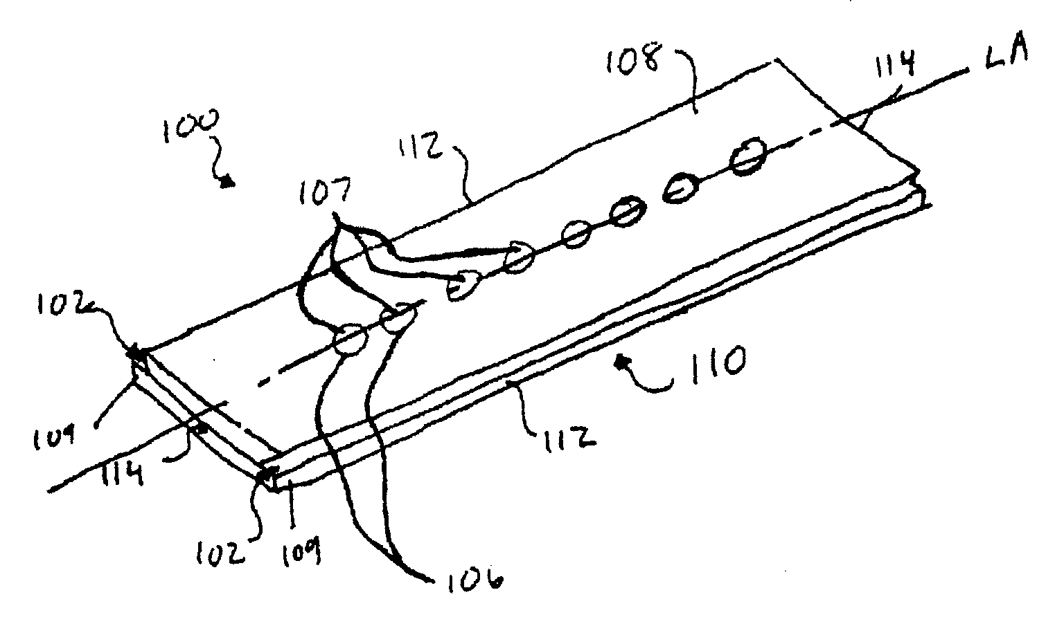
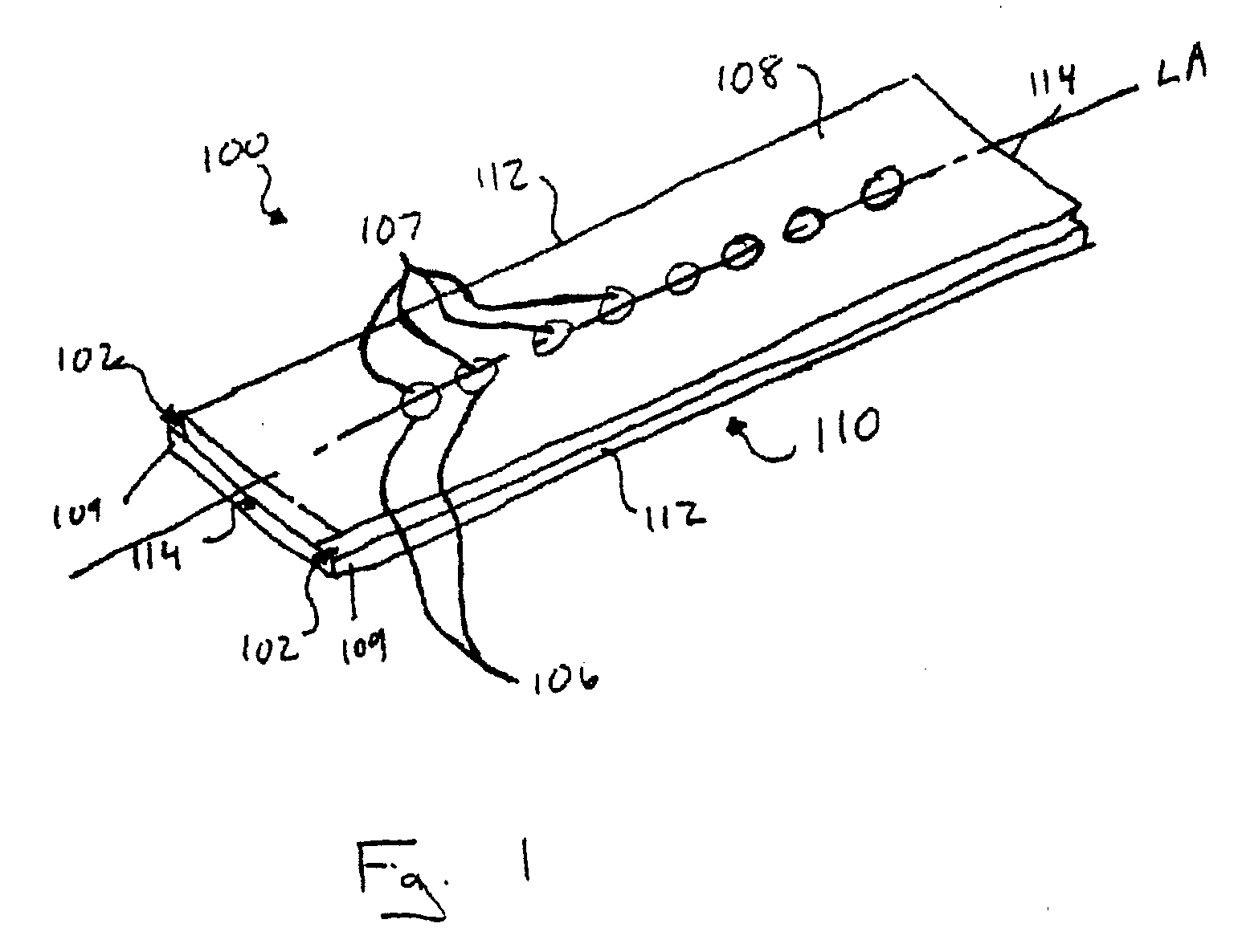
[0088]a mass spectrometer probe according to the present invention will hereafter be described with reference to FIGS. 1-2B.
[0089]As shown in FIG. 1, the probe 100, which is generally rectangular in shape, includes a top, sample presenting surface 108 and an opposite underside 110. The sample presenting surface 108 provides a plurality of locations 107 onto which a mass spectrometry sample may be provided. Of course, the locations 107 may be in the form of microwells, e.g., depressions formed in the sample presenting surface 108. Moreover, one or more of the locations may be circumscribed by a microstructure 106 such as a moat, which serves to facilitate maintaining a sample at a, particular location 107. Further, the locations 107 and / or microstructures 106 may be arranged in an array of addressable locations, e.g., a Cartesian coordinate system, thereby enabling a technician to track the location of particular samples on the sample presenting surface 108.
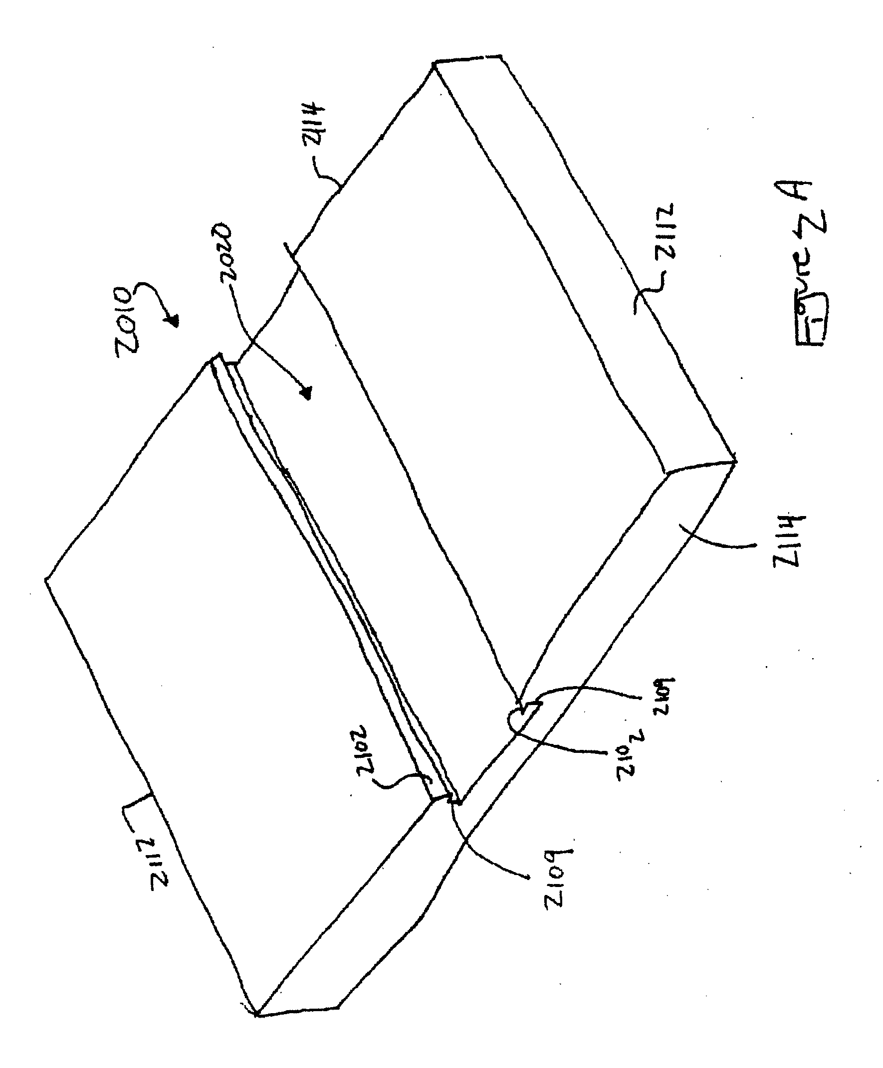
[0090]The perimeters of th...
second embodiment
[0093]a mass spectrometer probe according to the present invention will hereafter be described with reference to FIGS. 3-4B.
[0094]As shown in FIG. 3, the probe 300, which is generally tubular in shape, includes a top, sample presenting surface 308 and a rounded, oval-shaped underside 310. The sample presenting surface 308 provides a plurality of locations 307 onto which a mass spectrometry sample may be provided. Of course, the locations 307 may be in the form of microwells, e.g., depressions formed in the sample presenting surface 308. Moreover, one or more of the locations 307 may be circumscribed by a microstructure 306 such as a moat, which serves to facilitate maintaining a sample at a particular location 307. Further, the locations 307 and / or microstructures 306 may be arranged in a Cartesian coordinate system, thereby enabling a technician to track the location of particular samples on the sample presenting surface 308. The curved underside 310 is sized such that the probe 30...
third embodiment
[0097]a mass spectrometer probe according to the present invention will hereafter be described with reference to FIGS. 5-6B.
[0098]As shown in FIG. 5, the probe 500, which is disk-shaped, includes a top, sample presenting surface 508, an underside 510, a circular sidewall 512, and a post 514 from which spring-actuated buttons 516 project. The sample presenting surface 508 provides a plurality of locations 507 onto which a mass spectrometry sample may be provided. Of course, the locations 507 may be in the form of microwells, e.g., depressions formed in the sample presenting surface 508. Moreover, one or more of the locations 507 may be circumscribed by a microstructure 506 such as a moat, which serves to facilitate maintaining a sample at a particular location 507. Further, the locations 507 and / or microstructures 506 may be arranged in a Cartesian coordinate system, thereby enabling a technician to track the location of particular samples on the sample presenting surface 508.
[0099]T...
PUM
 Abstract
Description
Claims
Application Information
 - R&D
- Intellectual Property
- Life Sciences
- Materials
- Tech Scout
- Unparalleled Data Quality
- Higher Quality Content
- 60% Fewer Hallucinations
Browse by: Latest US Patents, China's latest patents, Technical Efficacy Thesaurus, Application Domain, Technology Topic, Popular Technical Reports.
© 2025 PatSnap. All rights reserved.Legal|Privacy policy|Modern Slavery Act Transparency Statement|Sitemap|About US| Contact US: help@patsnap.com