Lithography system, method of heat dissipation and frame

a technology of lithography and heat dissipation, applied in the field of lithography system, method of heat dissipation and frame, can solve the problems that technology does not address the fundamental problem of temperature stability and heat removal, and achieve the effects of superior heat dissipation capacity, superior heat dissipation coefficient, and superior heat absorption capacity

Active Publication Date: 2008-01-31
ASML NETHERLANDS BV
View PDF15 Cites 41 Cited by
  • Summary
  • Abstract
  • Description
  • Claims
  • Application Information

AI Technical Summary

Benefits of technology

[0015] The present invention provides a solution to the problem of heat transfer as described earlier, i.e. within a limited amount of space, with relatively high capacity and swift transfer of heat, without unduly complicating the process of loading or locating a target to be cooled within the stage of a direct write lithography machine.
[0017] It is thus understood by the invention that a phase transition in itself may be effectively used for absorbing heat from a lithography target. In a phase transition, to a lesser or larger extend, the temperature of the material in transition remains at least virtually constant, i.e. varies with a relatively much less extend than outside said phase transition, with sustained application of heat to said material. Surprisingly, by using this phenomenon for the purpose of heat removal, a very compact and sophisticated manner of cooling a lithography target is achieved.
[0018] It was found however, as an aspect underlying the invention, that materials providing superior capability of heat absorption without undue raise of temperature during such phase transition, could suffer from strongly limited thermal diffusivity, especially in a layer that had in mean time undergone the phase transition, the effect being that that overall thermal diffusivity of the material body is determined by said first transited layer. It is therefore a further aspect of the invention that such material of superior heat absorbing capacity is combined with a further material having a relatively superior coefficient of heat transport.

Problems solved by technology

This technology however does not address the fundamental problem of temperature stability and heat removal as desired by modern lithography systems.

Method used


Image

  • Lithography system, method of heat dissipation and frame
  • Lithography system, method of heat dissipation and frame
  • Lithography system, method of heat dissipation and frame

Examples


Embodiment Construction

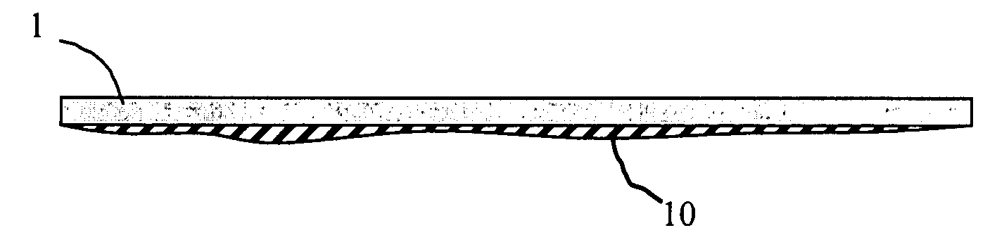
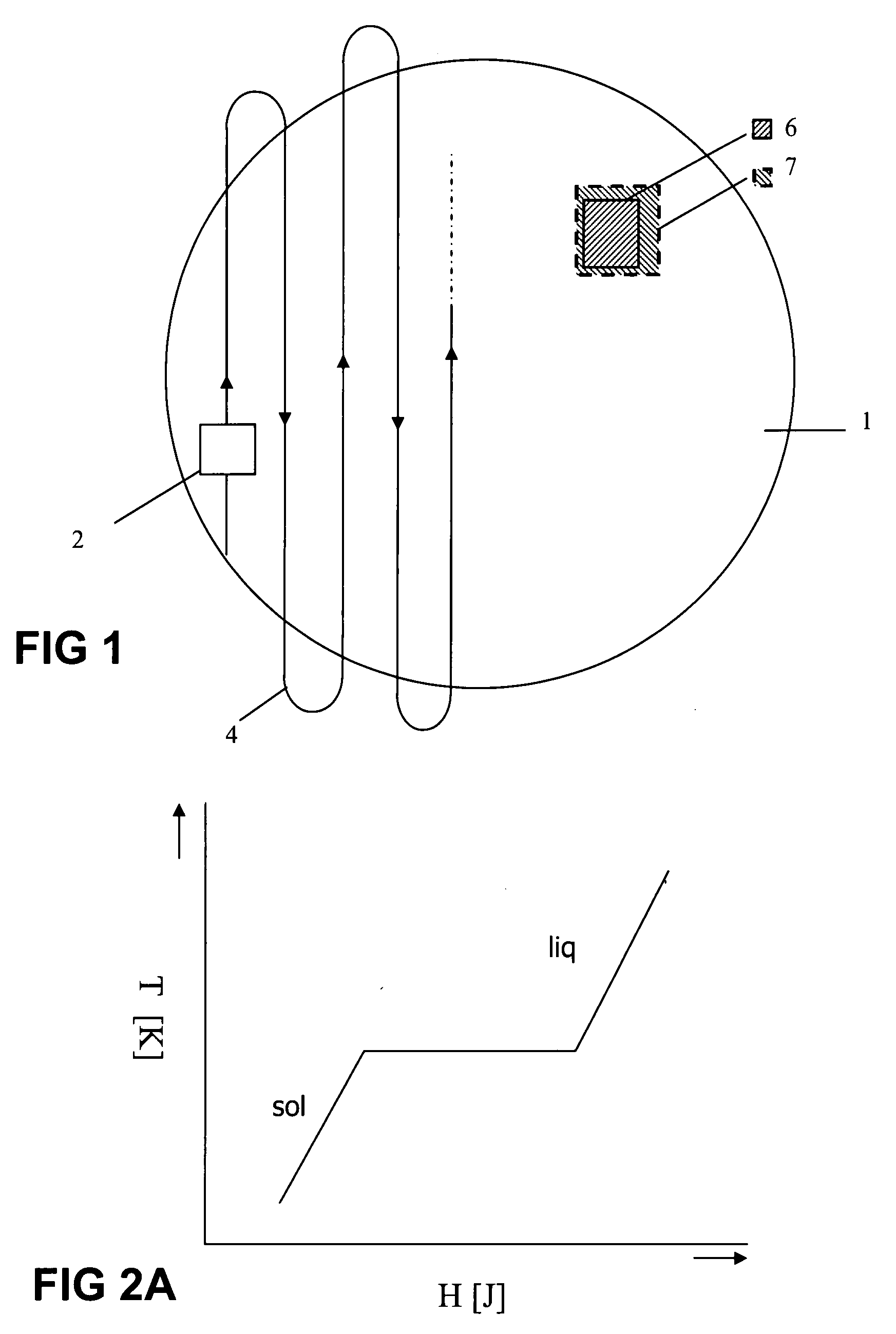
[0033]FIG. 1 shows a target, here in the form of a wafer 1, which moves relative to e.g. a charged particle beam column of a litho apparatus, or other kind of beam source for lithography, according to path 4, here indicating the centre of a lens assembly or slit 2, passing over several fields 6 of the wafer.

[0034] Due to induced heat to the wafer, by the incidence of said charged particle beams—the wafer will expand. This expansion results in a difference between the expected position and dimension of a die 6 and the actual position and dimension of a die 7. This difference will result in an overly error of the exposure pattern on the wafer.

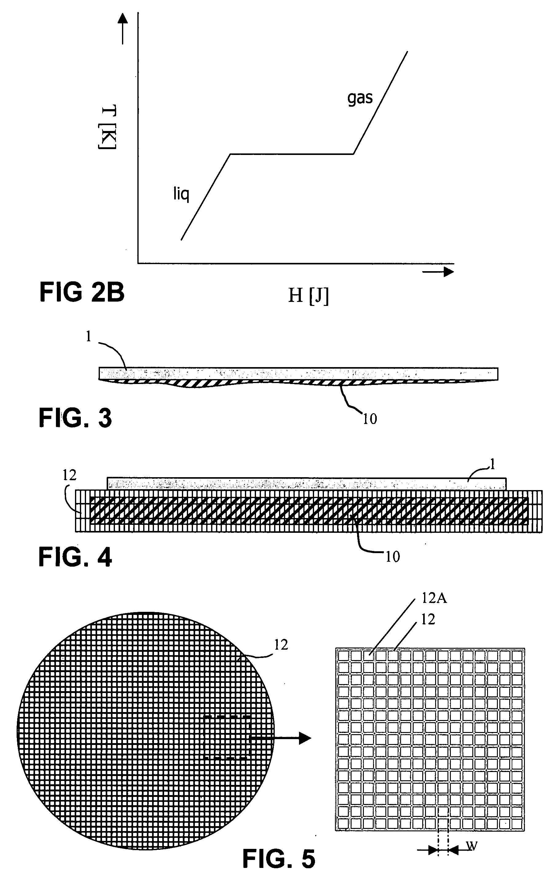
[0035] In accordance now with the present invention, heat removal from said wafer is realized by the use of a phase transition in a material—here also denoted as phase change material—that is brought into thermal contact with said target 1, e.g. as illustrated by any of the embodiments of FIG. 4.

[0036]FIG. 2 illustrates the principle of such p...


PUM


Abstract

The present invention relates to a lithography system for projecting an image or an image pattern on to a target such as a wafer. Energy that is accumulated in the target by the projection of the image or image pattern is removed from said target, such that expansion by local and / or overall heating is limited to a relevant pre-defined value, and wherein such heat removal is realised by the use of a phase transition in a heat absorbing material that is brought into thermal contact with said target. As a further elaboration, such material may be applied in combination with a further material having a superior coefficient of heat transport, and may be incorporated in an emulsion comprising a material having a superior coefficient of heat transfer. Said material may e.g. be adhered to a bottom face of the target, and may also be included in a frame.

Description

[0001] The present patent application is a non-provisional application claiming the priority of U.S. Provisional Application No. 60 / 833,865, filed Jul. 28, 2006.BACKGROUND OF THE INVENTION [0002] The present invention relates to a lithography system for projecting an image pattern on to a target surface such as a wafer. FIELD OF THE INVENTION [0003] Such systems are generally known, e.g. in the form of a mask writer or in the form of a lithography application as in WO 2004038509. In the example presented by the latter system, the target to be patterned is subjected to incidence of photons or charged particles such as ions and electrons. Due to the energy load of such particles or photons, inherent to the manner of extracting or emitting the same, the target is at least locally heated. Such heating, in accordance with an insight developed as part of the invention, becomes problematic when expansion of the target under influence by it's processing exceeds a pre-defined value. In gener...

Claims


Application Information

Patent Timeline
Patent Type & Authority Applications(United States)
IPC IPC(8): G03B27/42
CPCG03F7/70875
Inventor KRUIT, PIETERDANSBERG, MICHEL PIETERWIELAND, MARCO JAN-JACO
Owner ASML NETHERLANDS BV
Why Eureka
Try Eureka