[0010]Japanese Laid-Open Patent Publication No. 1999-329518, on the other hand, describes a power source which contains battery modules in three or more tiers within a holder case. In that power source, a plurality of battery modules, positioned in a parallel relationship relative to one another and separated along the blowing direction of cooling air, are contained within the holder case in a multi-tier manner. This power source allows the battery modules to be cooled by forcibly blowing the cooling air in between the battery modules. Disadvantageously, however, such a cooling structure is prone to make a cooling performance less efficient for a battery module in the downstream than for a battery module in the upstream, thus generating a higher temperature. To overcome such a shortcoming, the holder case has an air turbulence accelerator, such as a dummy battery unit, provided in the uppermost
stream so that a
stream of cooling air coming into the holder case may be disturbed for allowing the battery module in the upstream to be effectively cooled. Further, the holder case has an auxiliary air intake, provided intermediate in a path of the cooling air, for allowing the cooling air in, and thus a cooling effectiveness is enhanced for a battery in the downstream.
[0011]In the above-described power source, a
cooling effect for the battery module in the downstream can certainly be enhanced by means of the air turbulence or by the cooling air which is taken in intermediately. With such structure, however, it is impossible to cool all battery modules down to a uniform temperature.
[0012]The present invention has been made in order to solve such disadvantages. It is, therefore, the primary object of the present invention to provide an electric power source in which a plurality of batteries, contained within a holder case in a multi-tier manner, are cooled effectively and uniformly with a reduced
temperature difference among the batteries.
[0015]The above-described power source carries the
advantage that all batteries, being contained within a holder case in a multi-tier manner, can be cooled effectively and uniformly with a reduced
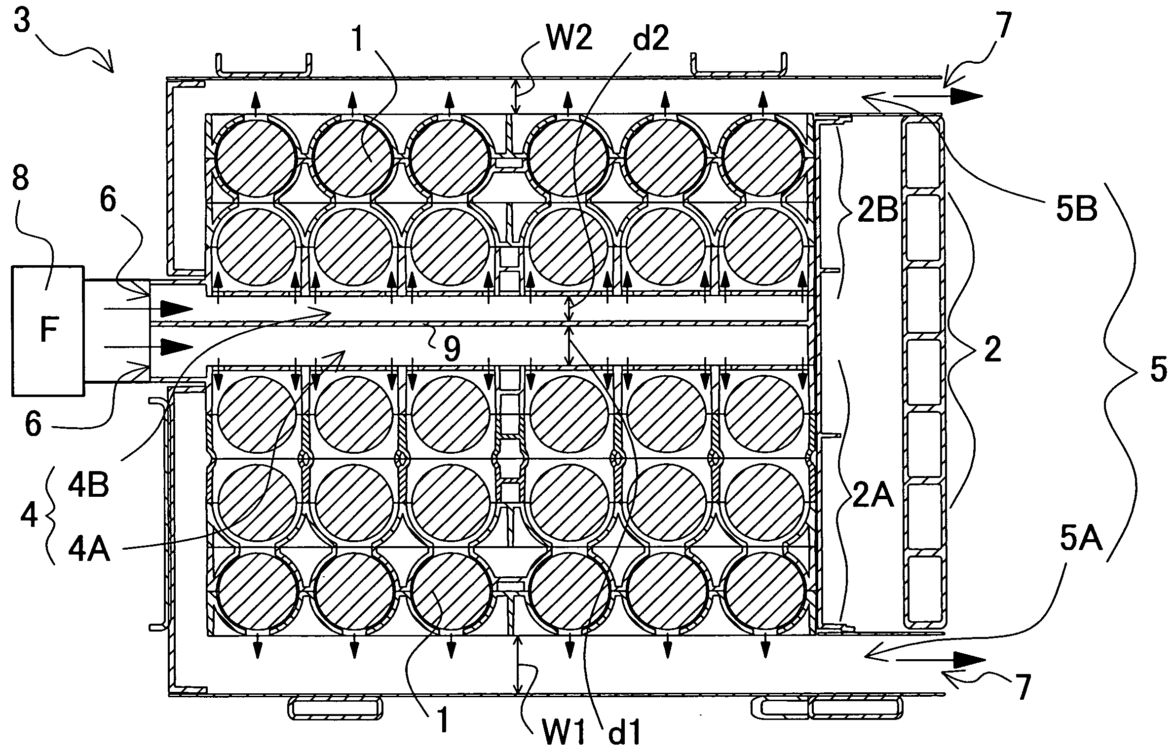
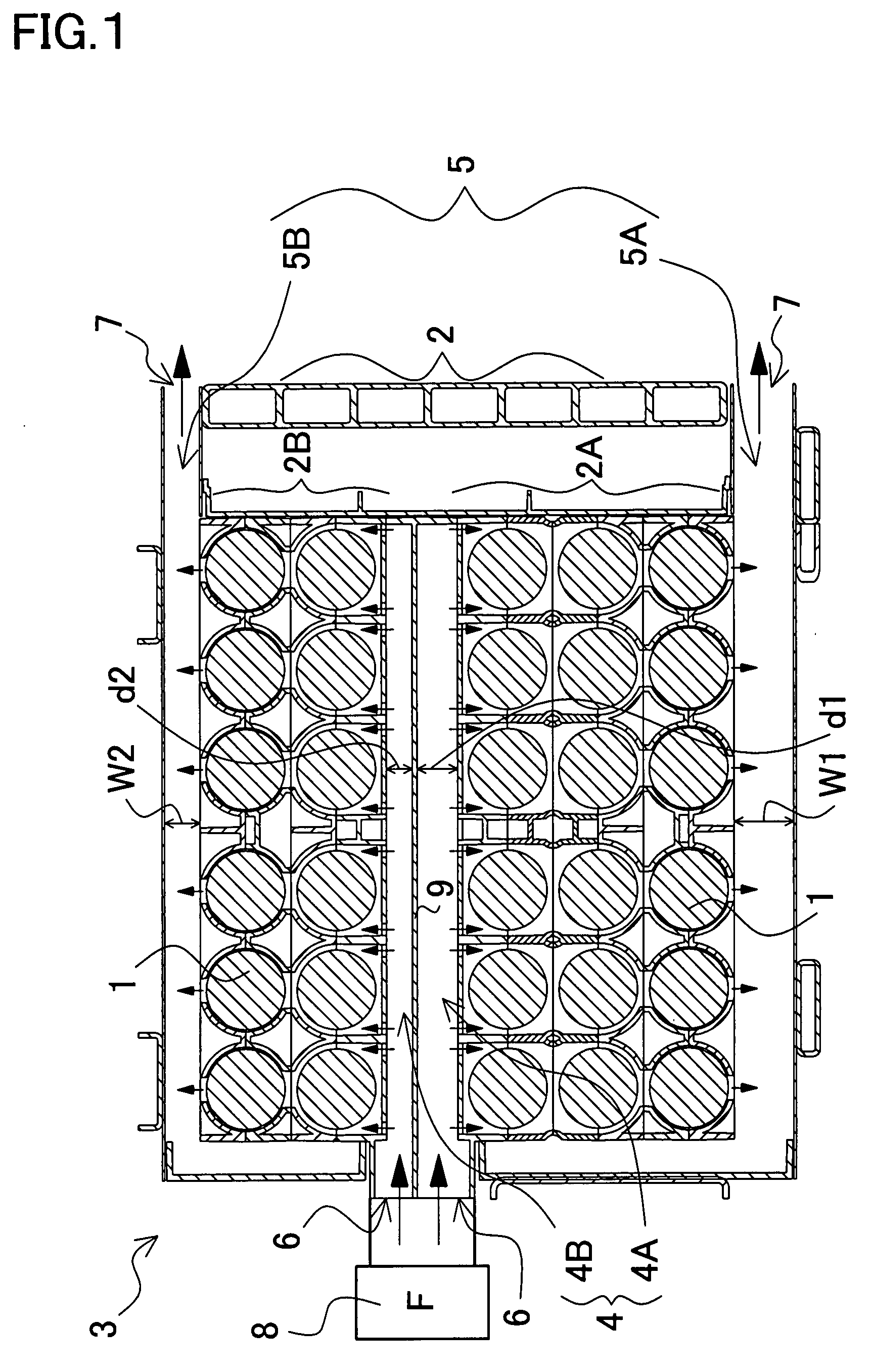
temperature difference among the batteries. This is made possible because the power source is so constructed and arranged that: (1) a plurality of batteries are stacked in two or more tiers within a battery case; (2) the battery case is divided midway into first and second sub holder cases; (3) an intermediary duct is provided between the divided first and second sub holder cases; (4) an outer duct is respectively provided outside each of the first and second holder cases, so that cooling air is allowed to flow from the intermediary duct through the holder case into the outer duct or alternatively from the outer duct through the holder case into the intermediary duct, for cooling the batteries contained in the holder case; and further, (5) the intermediary duct, being provided with a partition inside the duct, is so divided into first and second intermediary sub ducts that the first intermediary sub duct is connected to the first sub holder case while the second intermediary sub duct is connected to the second sub holder case. In particular, since the power source thus structured divides the batteries, contained in the battery case in a multi-tier manner, into the first and second sub holder cases, the number of batteries to be contained in each tier in the first and second sub holder cases becomes about half. For example, in a power source where batteries are contained in total five tiers, the batteries can be contained in the first sub holder case in three tiers, and in the second sub holder case in two tiers. Generally, n a structure where batteries stacked in five tiers are to be cooled by sequentially blowing cooling air, the batteries in the windward is effectively cooled by the cooling air, whereas the batteries in the leeward are to be less effectively cooled down due to warmed-up air. In the case of the inventive power source, however, the 5-tiered batteries, being divided into three and two tiers, are forcibly blown by the cooling air, the batteries can be cooled uniformly in the windward and in the leeward, with a reduced
temperature difference among the batteries. In particular, since the intermediate duct is provided between the segmented first and second sub holder cases to which the intermediary duct is respectively connected for blowing the cooling air through, the batteries contained in the first and second sub holder cases, being placed between the intermediary duct and the outer duct, can be uniformly cooled by forcibly blowing the cooling air.
[0017]By way of example, to cool the batteries uniformly, a power source containing batteries in total four tiers may have the batteries divided in the sub holder cases into two and two tiers respectively; a power source containing batteries in total five tiers may have the batteries divided in the sub holder cases into three and three tiers respectively; and a power source containing batteries in total seven tiers may have the batteries divided in the sub holder cases into four and three tiers respectively. In particular, by using the partition provided inside the intermediary duct, the inventive power source is featured in that an optimal amount of cooling air can be forcibly blown to correspond with the number of tiers in which to stack the batteries contained in each sub holder case, so that all the batteries can be cooled down to a more uniform temperature, with a reduced temperature difference among the batteries.

