Hollow member, manufacturing method thereof, fluid distribution system using the hollow member, and forming apparatus of hollow material

a technology of hollow member and manufacturing method, which is applied in the field of hollow member, can solve the problems of increased plate thickness of the entire catalyst container, increased weight of the catalyst container, and possible leakage of exhaust gas or the like which needs to be treated,

Inactive Publication Date: 2008-02-07
TOYOTA JIDOSHA KK
View PDF1 Cites 4 Cited by
  • Summary
  • Abstract
  • Description
  • Claims
  • Application Information

AI Technical Summary

Benefits of technology

[0018] In light of the foregoing problems, it is one object of the invention to facilitate control of plate thickness and control of shape when manufacturing a hollow member, for example, a container of a catalytic converter used in an exhaust pipe of a combustion engine. It is a further object to provide an apparatus for stably supplying a hollow member having good airtightness, and a fluid distribution system using such a hollow member, and also forming the hollow material easily (the relation between a hollow member and hollow material will be described in detail in “Description of the Preferred Embodiment”), by decreasing adverse effects of a hollow member due to insufficient control of plate thickness and a fluid distribution system using such a hollow member (by way of example, in a catalyst container, radiant noise increases due to exhaust resistance in the case of a decrease of plate thickness, or the weight of catalyst container increases in the case of an increase of plate thickness).
[0021] Mush seam welding (also known as “mush-room welding”) is a type of resistance welding, and a method in which two material plates such as steel plates are overlaid slightly at the edges at a specific width and the overlapped portions are pressed and energized from upper and lower portions by circular revolving electrodes, and the work is relatively moved to weld continuously. A high welding strength and sealing effect can be obtained, and as a result of the press of the overlapped portions, the thickness of the overlapped portions can be smaller than the sum of the plate thicknesses of two material plates such as steel plates before welding. Therefore, by joining individual plates different in thickness or material by mush seam welding, a plate member with flat junctions and high welding strength can be obtained. Further, such mush seam welding may be also applied in the joining of mutually opposing axial side ends of plate materials when forming a hollow member with a bending plate member so that a hollow material of flat junctions may be formed without sacrificing welding strength or the like at the junctions.
[0026] As mentioned above, by mush seam welding, a high welding strength and sealing effect can be obtained, and as a result of the press of the overlapped portions, the thickness of the overlapped portions can be smaller than the sum of plate thicknesses of two material plates such as steel plates before welding. Therefore, by joining plates different in thickness or material by mush seam welding, plate members of flat and smooth junctions and high welding strength can be obtained. Such mush seam welding may be also applied in the joining of mutually opposing axial side ends of a plate material when a hollow material is formed by bending plate members, so that a hollow material of flat and smooth junctions may be formed without sacrificing welding strength or the like at the junctions.
[0029] According to such a forming apparatus, a plurality of material plates that are different in plate thickness or material are held by overlaying the junction sides by the flat plate member holding device, and are relatively moved in the mush seam welding direction with respect to the third electrode by the mush seam welding direction moving device. The mutually overlaid junction sides of the plate materials are continuously welded and joined while being squeezed between the first electrode and third electrode for mush seam welding provided in the flat plate member holding device, and plate members that are partially different in plate thickness or material are formed. The joined plate members are bent by the bend forming device, and held by overlaying the mutually opposing axial sides by the bent plate member holding means, and move relatively in the mush seam welding direction with respect to the third electrode by the mush seam welding direction moving device. The mutually opposing axial junction sides of the bent plate members are continuously welded and joined, being squeezed between the second electrode and third electrode for mush seam welding provided in the mush seam welding direction moving device so that the hollow material of high joining strength partially different in plate thickness or material is formed integrally. Since the other electrode (third electrode) of a pair of electrodes for mush seam welding is commonly used in the joining of material plates and in the joining of axial sides of bent plate members, and the forming apparatus of a hollow material is reduced in size.

Problems solved by technology

With such measure, however, the plate thickness of the entire catalyst container is increased more than necessary and the weight of the catalyst container is increased.
Such problems similarly occur when spinning the hollow material formed as disclosed in Japanese Patent Application Laid-Open No. 11-324637.
However, when the roundness is disturbed due to a step or the like formed in the peripheral direction of the junction of the hollow member, the fluid of exhaust gas or the like which needs to be treated may leak through the step without passing through the catalyst carrier.
Further, there is a problem that the appearance of the product is poor when such a step is formed outside of the hollow member.
On the other hand, in the case of forming a hollow material by joining material plates to form a plate member and bending the plate member and joining the opposing sides, a mush seam welding machine for joining plate members, and another mush seam welding machine for joining the opposing sides of the bent plate member are provided individually, and there is a problem that the equipment for forming such a hollow material becomes large, and the manufacturing cost cannot be reduced.

Method used


Image

  • Hollow member, manufacturing method thereof, fluid distribution system using the hollow member, and forming apparatus of hollow material
  • Hollow member, manufacturing method thereof, fluid distribution system using the hollow member, and forming apparatus of hollow material
  • Hollow member, manufacturing method thereof, fluid distribution system using the hollow member, and forming apparatus of hollow material

Examples


Embodiment Construction

[0062] In the following description and the accompanying drawings, the present invention will be described in more detail in terms of preferred embodiments.

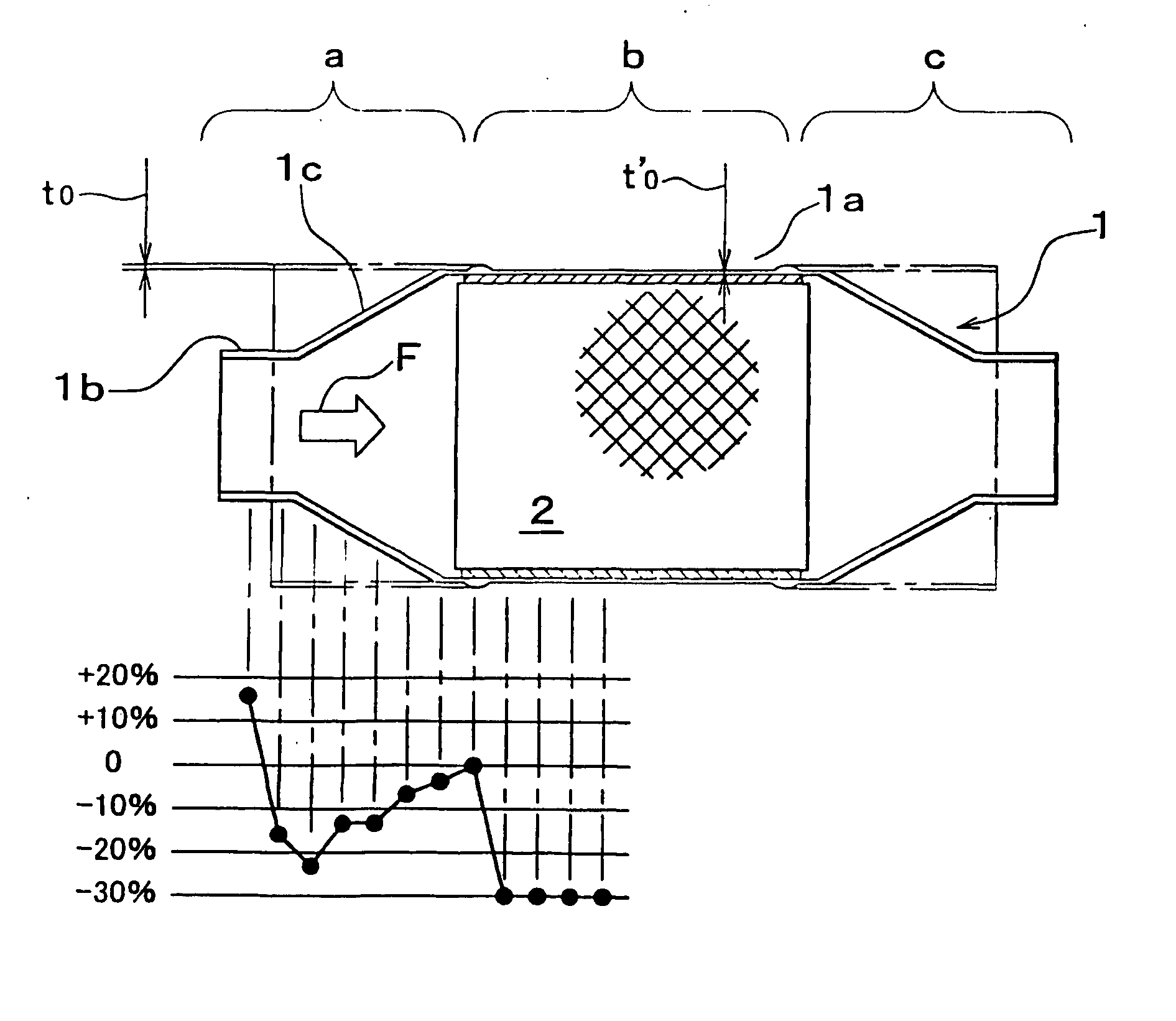
[0063] An embodiment of the invention will be explained below according to the accompanying drawings, in which the fluid distribution system is an exhaust system for purifying the exhaust gas of a combustion engine such as an internal-combustion engine, and the hollow member is a catalyst container 1 of a catalytic converter for holding a catalyst carrier inside. Herein, the same parts as in the conventional art are identified with same reference numerals and detailed description is omitted. In this explanation, a cylindrical member in the process is called a “hollow material”, and a changed cylindrical member being drawn in the sectional shape after completion of the spinning process for forming the hollow material into a predetermined shape is called a “hollow member”.

[0064]FIG. 1 shows a sectional view of a catalytic convert...


PUM

PropertyMeasurementUnit
thicknessaaaaaaaaaa
thicknessaaaaaaaaaa
shapeaaaaaaaaaa

Abstract

A manufacturing method of a catalyst container includes forming a plate member that is partially different in plate thickness or material by joining material plates that are different in plate thickness or material by welding; bending the plate member that is partially different in plate thickness or material to form a hollow material, wherein the hollow material is formed by bending the plate member and joining opposing sides thereof by welding; and changing a sectional shape of the hollow material by a spinning process.

Description

[0001] This is a Division of application Ser. No. 10 / 362,834 filed Feb. 27, 2003. The disclosure of the prior application is hereby incorporated by reference herein in its entirety. [0002] This application is the U.S. National Stage of PCT / IB01 / 01617, filed Sep. 5, 2001, which claims priority from JP2000-270255, filed Sep. 6, 2000, and JP2001-182065, filed Jun. 15, 2001, the disclosures of which are incorporated herein in their entireties by reference thereto.BACKGROUND [0003] 1. Field of the Invention [0004] The present invention relates to a hollow member, a manufacturing method thereof, a fluid distribution system using the hollow member, and a forming apparatus of a hollow material. [0005] 2. Description of Related Art [0006] A fluid distribution system for distributing a specific gas and changing its composition in the process of distribution is widely employed in various technical fields. By way of example, in a combustion engine such as an internal-combustion engine, an exhau...

Claims


Application Information

Patent Timeline
Patent Type & Authority Applications(United States)
IPC IPC(8): B23P11/00B21D22/14B21C37/08B21C37/15B21D22/18B21D41/04B21D51/18B21D53/84B21D53/88B23K11/00B23K11/06B23K11/20F01N3/28
CPCB21C37/065Y10T29/49826B21C37/0815B21C37/15B21D22/18B21D53/88B23K11/0026B23K11/063B23K11/065B23K2201/006B23K2201/04F01N3/2842F01N2450/02Y10T29/49345B21C37/0803B23K2101/006B23K2101/04B21D22/14B21D51/10B21K11/00
Inventor UMEDA, MASAHIROYOSIMOTO, KENJIISHIZU, SEIJIONUMA, MASASHIOYAMA, TSUYOSHI
Owner TOYOTA JIDOSHA KK
Why Eureka
Try Eureka